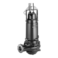
4.2.1 Wiring diagram
Standard power cable
V1
U1W1
V2
U2W2
V1
U1
W1
V2
U2
W2
V1
U1
W1
V2
U2
W2
1
2
3
4
5
6
V1
U1
W1
V2
U2
W2
TM055943
Wiring diagram for standard power cable
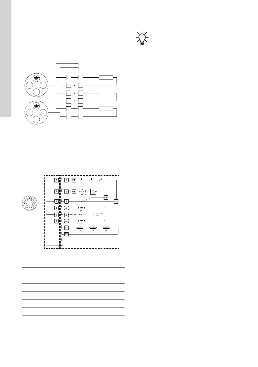
4.2.2 Sensors
TM051641
Wiring diagram for sensors
Pos. Description
TB Terminal board connection
PtS Pt100 in stator
PtL Pt100 in lower bearing
4 Thermal switches
TS Thermistors
MS
Moisture switches
Two moisture switches in Ex pumps
The wiring diagrams in custom-built prod-
ucts may differ from the standard. In this
case, contact the nearest Grundfos com-
pany or authorised workshop.
22
English (GB)
 Loading...


