Pos. Description
1 0.7
2 Set screw
3 Fastening screw
4 Fastening screw
8.4.2 Dry-installed pumps, installation types D
and H
Depending on the pump range, there are two ways to
set the impeller clearance. Method 1 is for range
50-54 and method 2 is for range 58-70.
Method 1
Do not use undue force when tightening
the fastening screws as this may damage
the bearings. The movement is usually 1
to 3 mm.
1. Loosen the set screws by two full turns for each.
2. Close the impeller clearance by lightly tightening
the fastening screws diagonally until the impeller
reaches the pump housing.
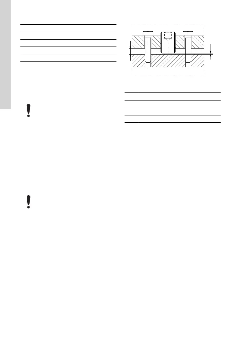
3. Loosen the fastening screws to make a 0.7 mm
gap under the heads of the fastening screws. See
fig. Impeller clearance adjustment.
4. Tighten the set screws tightly.
5. Tighten the fastening screws diagonally.
Method 2
Do not use undue force when tightening
the fastening screws as this may damage
the bearings. The movement is usually 1
to 3 mm.
1. Loosen the six fastening screws and close the
impeller clearance by tightening the three set
screws. Tighten the screws diagonally to move
the inlet cover evenly.
2. Measure the distance "L" between the inlet cover
and pump housing at three points next to the set
screws, using feeler gauges or calipers, then note
the distance.
3. Loosen the set screws and draw back the inlet
cover between 0.5 and 0.9 mm using the six
fastening screws (approximately one 270° turn of
an M12 fastening screw) and the distance "L" as
reference. See fig. Impeller clearance adjustment.
4. Tighten all set screws and check that the distance
"L" at the three reference points is stable at the
new value.
TM051915
Impeller clearance adjustment
Pos. Description
1 Set screw
2 Fastening screw
H 0.5 - 0.9
Related information
8.4.1 Submersible pumps, installation types S, C
and ST
8.5 Pump cleaning and inspection
Clean the pumps at regular intervals. In case of wet-
installed pumps, lift the pumps out of the pit and clean
them on site. Hose down the pump externally using a
high-pressure jet cleaner at a maximum of 100 bars.
Remove caked dirt from the motor to ensure proper
heat conductivity. A mild detergent approved for
disposal into the sewage system can be used. The
pumps can be scrubbed, using a soft brush, if
necessary.
Visual inspection of the pump must include the
following:
• Search for cracks or other external damage.
• Check the lifting bracket and lifting chain for wear
and corrosion.
• Make sure the motor cables are not damaged.
• Inspect visible parts of the cable entries for
cracks.
• Check if the cables are firmly connected to the
motor top cover.
• Check all visible screws for self-loosening and
tighten, if necessary.
The pumps are fitted with a vent valve at the top of
the cooling jacket. The valve may be removed and
cleaned, if necessary. Clean the vent hole before
refitting the valve.
8.6
Motor cables
Use only suitable and manufacturer-approved cables.
36
English (GB)
 Loading...


