7. Replace the O-rings, refit screw C and tighten
securely. Fill the oil chamber with oil to the correct
level. Refit screws A and B and tighten them
securely.
Vertical position
Proceed as follows:
1. Identify the screws A, B and C. See fig. Pump with
inspection screw A upwards.
TM024005
Oil level of a vertical pump
2. Use screw B for indication of the oil level in the oil
chamber. See fig. Oil level of a vertical pump.
3. When the pump is vertical, the oil has to be
pumped out of the oil chamber. Use a suction
pump with a flexible suction hose that can be
inserted deep into the oil chamber.
4. Pump out the oil using all the screw holes in turns
to reach all sections of the oil chamber. Collect the
drained oil in a clean container.
5. Replace the O-rings, refit screw C and tighten
securely. Fill the oil chamber with oil to the correct
level. Refit screws A and B and tighten them
securely.
8.4
Inspection and adjustment of the
impeller clearance
The impeller clearance must be set to 0.7
mm ± 0.2 mm. It must be checked at least
3 different points.
The correct axial clearance is 0.7 mm ± 0.2 mm.
Reset the clearance if it is 0.7 mm or more. The
method for resetting the clearance is different for
submersible pumps, installation types S, C and ST,
and for dry-installed pumps, installation types D and
H.
8.4.1
Submersible pumps, installation types S, C
and ST
Submersible pumps have a separate, adjustable
pump inlet cover, which may be shaped as an inlet
bell. Locate the six fastening screws of the inlet cover
and the three set screws.
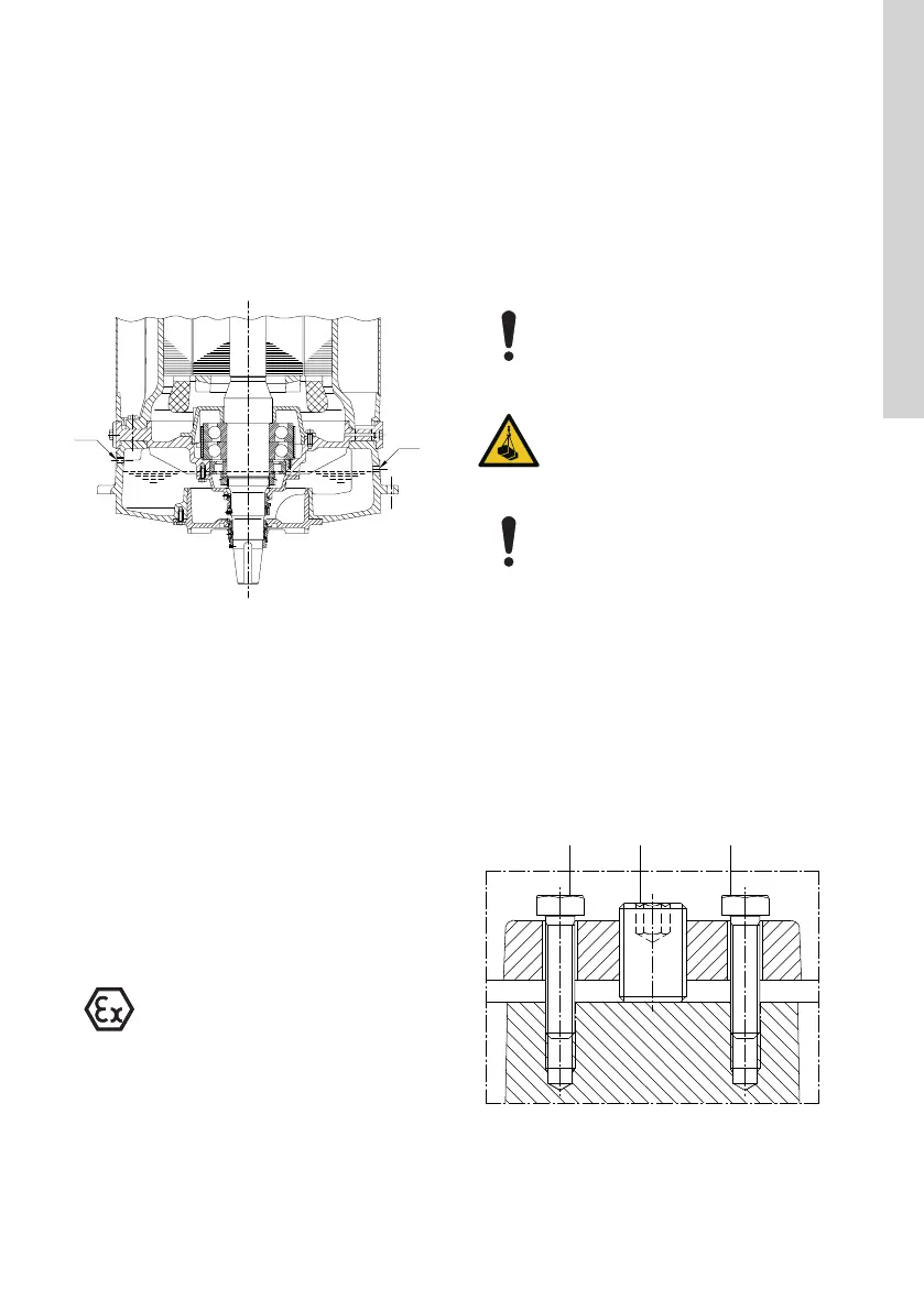
Use a feeler gauge to check the clearance between
the impeller and the inlet cover all around the
perimeter of the inlet opening. See fig. Impeller
clearance adjustment.
Do not use force when tightening the fas-
tening screws as this may damage the
bearings. The movement is usually 1 to 3
mm.
DANGER
Overhead load
Death or serious personal injury
‐ Never work under a pump when it is
hanging from a crane.
Before adjusting the clearance, clean the
gap between the impeller and the inlet
cover.
1. Loosen the set screws by two full turns for each.
2. Close the impeller clearance by lightly tightening
the fastening screws diagonally until the impeller
reaches the pump housing.
3. Loosen the fastening screws to make a 0.7 mm
gap under the heads of the fastening screws. See
fig. Impeller clearance adjustment.
4. Tighten the set screws tightly.
5. Tighten the fastening screws diagonally.
TM051916
Impeller clearance adjustment
35
English (GB)
 Loading...


