5.5 Switches and sensors
The pump must not run dry.
Install an additional level switch to ensure the pump is
stopped in case the primary stop level switch is not
operating.
The pump includes the following switches and
sensors:
• three thermal switches or three thermal protectors
in the stator windings
• moisture switches:
- in range 50-70: one under the motor top cover
- in Ex pumps, range 50-58 and 70: one under
the motor top cover and one in the stator
housing
- in Ex pump, range 62: two under the motor top
cover.
• one optional Pt100 sensor in the bearing or in the
stator winding
• one analog and optional WIO sensor in the oil
chamber.
TM032802
Sensor cable
Pos. Description
1 Yellow and green
TM046067
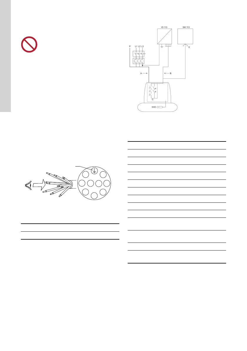
Sensor connections, SM 113 outside the motor
Analog and digital outputs
Symbol Description
A Power side
B Signal side
C "db" enclosure
WIO "eb" and "mb" approval
T Thermal switch
M Moisture switch
P Power input
S Sensor input
SM 113 Sensor board
IO 113
IO 113 with internal alarm relay (250
VAC)
"db"
Flameproof enclosure of the motor sec-
tion
"mb" WIO sensor protection by encapsulation
"eb"
WIO sensor protection by increased
safety
26
English (GB)
 Loading...


