English (GB)
4
2.2.1 Shaft seal
Mechanical shaft seal with assembly length to EN 12756.
The following variants are available as standard:
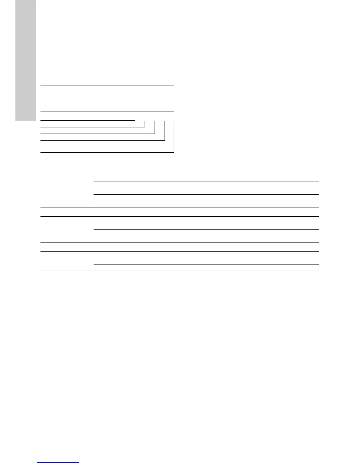
2.2.2 Codes for shaft seal
The positions (1) - (4) cover four pieces of information about the
shaft seal:
The following table explains the positions (1), (2), (3) and (4).
Pump Shaft diameter Variant code
TP Series 300,
flange
∅ 28
∅ 38
∅ 48
∅ 55
∅ 60
BAQE
BQQE
GQQE
Example (1) (2) (3) (4)
Grundfos type designation
Material, rotating seal face
Material, stationary seat
Material, secondary seal and other rubber and plastic parts,
excluding the neck ring
Position Type Short description of seal
(1)
A O-ring seal with fixed driver
B Rubber bellows seal
D O-ring seal, balanced
G Bellows seal, type B, with reduced seal faces
R O-ring seal, type A, with reduced seal faces
Position Type Material
(2) and (3)
A Carbon, metal-impregnated (antimony)
B Carbon, resin-impregnated
U Tungsten carbide
Q Silicon carbide
Position Type Material
(4)
EEPDM
FFXM
V FKM

 Loading...


