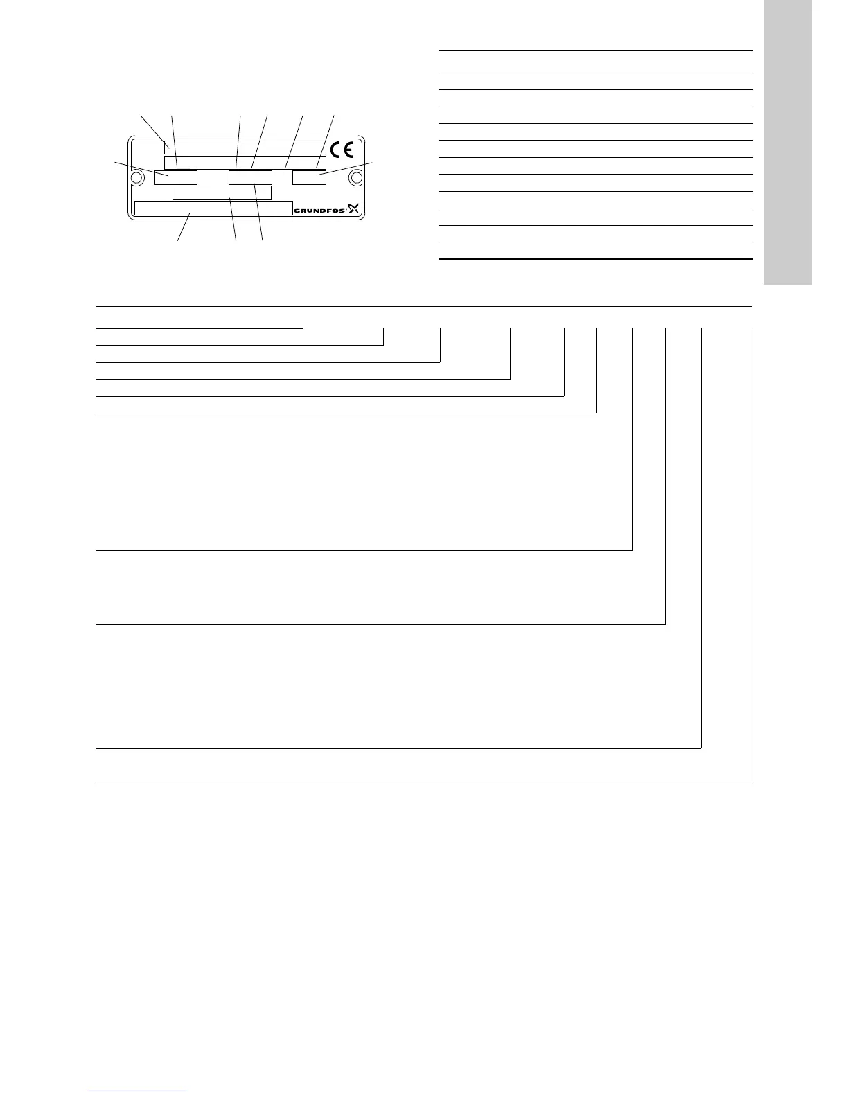
Pos. Description
1 Type designation
2 Model
3 Product number
4 Place of production
5 Production year and week
6 Serial number
7 Maximum pressure and temperature
8 Rated flow rate
9 Head at rated flow rate
10 Speed
11 Country of production
Example TP D 65 -550 /2 -A -F -A -BAQE
Type range
Twin-head pump
Nominal diameter of suction and discharge flanges (DN)
Maximum head [dm]
Number of motor poles
Pump version
A = Basic version
– Union connection with nut for G 1 1/2 or G 2
– Flange connection to ISO 7005-2, PN 6, PN 10, PN 6/PN 10, PN 16 and PN 25
– Mounting designation: IM 3001 (IM B 5)/IM 3011 (IM V 1)
– The pump housing has tapped holes for mounting the pump on a base plate or bracket.
I = PN 6 flange
X = Used when codes do not fully cover the actual version.
U = NEMA standard
Pipe connection
F = DIN flange
J = JIS flange
G = ANSI flange
R = External thread
Materials
A = Basic version
– Pump housing: grey cast iron EN-GJL-250, DIN W.-Nr. EN-JL1040
– Motor stool: grey cast iron EN-GJL-250, DIN W.-Nr. EN-JL1040
– Pump shaft: stainless steel DIN W.-Nr. 1.4436/DIN W.-Nr. 1.0037
– Impeller: grey cast iron EN-GJL-200, DIN W.-Nr. EN-JL1030
Z = TP Series 100 and 200: bronze pump housing and motor stool
B = TP Series 300: bronze impeller
Shaft seal and plastic/rubber parts, excluding the neck ring
See section 2.2.1 Shaft seal.

 Loading...


