English (GB)
10
The operating voltage and frequency are marked on
the pump nameplate. Make sure that the motor is
suitable for the power supply on which it will be used.
Single-phase standard motors incorporate a thermal
switch and require no additional motor protection.
Three-phase motors must be connected to a motor
starter.
Motors of 3 kW and up incorporate thermistors
(PTC). The thermistors are designed according to
DIN 44082.
The electrical connection should be carried out as
shown in the diagram inside the terminal box cover.
The motors of twin-head pumps are to be connected
separately.
6.1 Frequency converter operation
Grundfos motors:
All three-phase Grundfos motors from frame size 90
and up can be connected to a frequency converter.
The connection of a frequency converter will often
have the effect that the motor insulation system is
loaded more and that the motor will be more noisy
than during normal operation. In addition, large
motors are loaded by bearing currents caused by the
frequency converter.
In the case of frequency converter operation, the
following should be considered:
• In 2-, 4- and 6-pole motors of 45 kW and up, one
of the motor bearings should be electrically
isolated to prevent damaging currents from
passing through the motor bearings.
• In the case of noise-critical applications, the
motor noise can be reduced by fitting a dU/dt
filter between the motor and the frequency
converter. In particularly noise-critical
applications, it is recommended to fit a sinusoidal
filter.
• The length of the cable between motor and
frequency converter affects the motor load. It
should therefore be checked that the cable length
meets the specifications laid down by the
frequency converter supplier.
• For supply voltages between 500 and 690 V,
either a dU/dt filter should be fitted to reduce
voltage peaks or a motor with reinforced
insulation should be used.
• For supply voltages of 690 V, a motor with
reinforced insulation should be used and a dU/dt
filter should be fitted.
6.1.1 Other motor makes than Grundfos
Contact Grundfos or the motor manufacturer.
7. Start-up
7.1 Priming
Closed systems or open systems where the
liquid level is above the pump inlet:
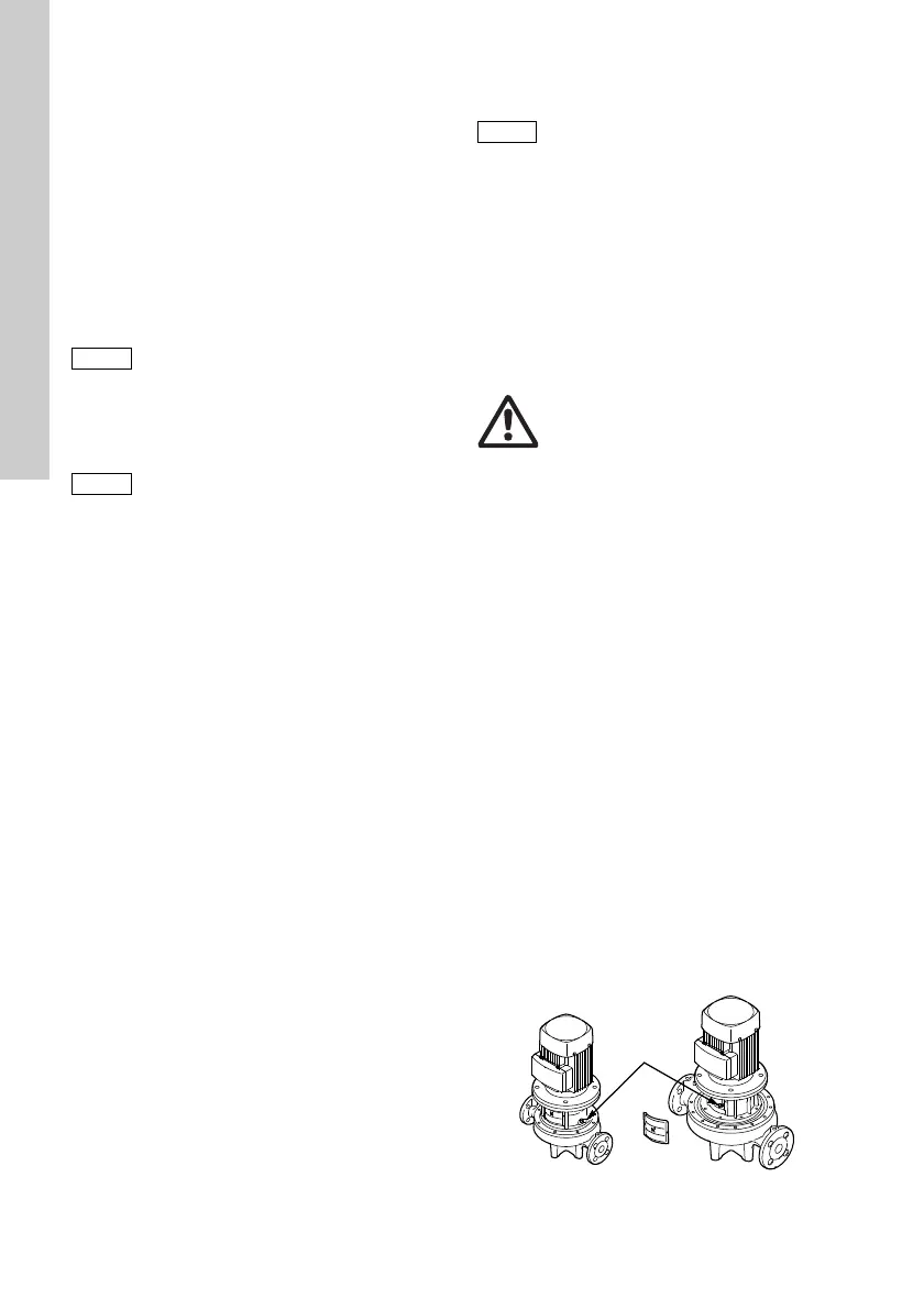
1. Close the discharge isolating valve and loosen
the air vent screw in the motor stool. See fig. 13.
2. Slowly open the isolating valve in the suction
pipe until a steady stream of liquid runs out of the
vent hole.
3. Tighten the air vent screw and completely open
the isolating valve(s).
Open systems where the liquid level is below the
pump inlet:
The suction pipe and the pump must be filled with
liquid and vented before the pump is started.
1. Close the discharge isolating valve and open the
isolating valve in the suction pipe.
2. Loosen the air vent screw. See fig. 13.
3. Remove the plug from one of the pump flanges,
depending on the pump location.
4. Pour liquid through the priming port until the
suction pipe and the pump are filled with liquid.
5. Replace the plug and tighten securely.
6. Tighten the air vent screw.
The suction pipe can to some extent be filled with
liquid and vented before it is connected to the pump.
A priming device can also be installed before the
pump.
Fig. 13 Position of air vent screw
Do not start the pump until it has been
filled with liquid and vented.
Motors types MEZ 63, MG 71 and MG 80
for supply voltages up to and including
440 V (see motor nameplate) must be
protected against voltage peaks higher
than 650 V between the supply
terminals.
Do not start the pump until it has been
filled with liquid and vented. To ensure
correct venting, the vent screw should
point upwards.
Warning
Pay attention to the direction of the
vent hole, and ensure that the escaping
liquid does not cause injury to persons
or damage to the motor or other
components.
In hot-liquid installations, pay special
attention to the risk of injury caused by
scalding hot liquid.
In cold-liquid installations, pay special
attention to the risk of injury caused by
the cold liquid.
TM03 8126 0507

 Loading...


