English (GB)
9
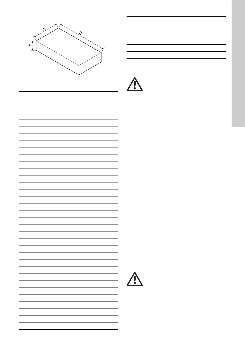
Fig. 12 Foundation for TP(D) Series 300 pumps
5.4 Terminal box positions
The terminal box can be turned to any of four
positions, in 90 ° steps.
Change the terminal box position as follows:
1. If necessary, remove the coupling guards using
a screwdriver. Do not remove the coupling.
2. Remove the screws securing the motor to the
pump.
3. Turn the motor to the required position.
4. Replace and tighten the screws.
5. Replace the coupling guards.
5.5 Base plate
Single-head pumps (except TP 25-50, 25-90, 32-50,
32-90, 40-50 and 40-90) have two tapped holes in
the bottom of the pump housing which can be used
for fitting a Grundfos base plate to the pump.
The base plate is available as an optional extra.
Twin-head pumps have four tapped holes in the
bottom of the pump housing. For some twin-head
pumps, a base plate consisting of two halves is
available.
Base plates with dimensions are shown on page 41.
5.6 Frost protection
Pumps which are not being used during periods of
frost should be drained to avoid damage.
6. Electrical connection
The electrical connection should be carried out in
accordance with local regulations.
TM03 9190 3607
Concrete foundation dimensions
Pump
weight
[kg]
Y
(height)
[mm]
Z
(length)
[mm]
X
(width)
[mm]
150 280 565 565
200 310 620 620
250 330 670 670
300 360 710 710
350 375 750 750
400 390 780 780
450 410 810 810
500 420 840 840
550 440 870 870
600 450 900 900
650 460 920 920
700 470 940 940
750 480 970 970
800 490 990 990
850 500 1010 1010
900 510 1030 1030
950 520 1050 1050
1000 530 1060 1060
1050 540 1080 1080
1100 550 1100 1100
1150 560 1100 1100
1200 560 1130 1130
1250 570 1150 1150
1300 580 1160 1160
1350 590 1180 1180
1400 600 1190 1190
1450 600 1200 1200
1500 610 1220 1220
1550 620 1230 1230
1600 620 1250 1250
1650 630 1250 1250
1700 635 1270 1270
Warning
Before starting work on the pump,
make sure that the power supply has
been switched off and that it cannot be
accidentally switched on.
Warning
Before removing the terminal box cover
and before any removal/dismantling of
the pump, make sure that the power
supply has been switched off.
The pump must be connected to an
external mains switch with a minimum
contact gap of 3 mm in all poles.
Concrete foundation dimensions
Pump
weight
[kg]
Y
(height)
[mm]
Z
(length)
[mm]
X
(width)
[mm]

 Loading...


