5.3 Checking the direction of rotation
Do not start the pump to check the direction of
rotation until it has been filled with liquid.
Do not check the direction of rotation with
the motor alone, as an adjustment of the
shaft position is required when the
coupling has been removed.
The correct direction of rotation is shown by arrows
on the motor fan cover or on the pump housing.
5.4 Starting up the pump
WARNING
Escaping liquid
Death or serious personal injury
‐ Pay attention to the orientation of the
vent hole to ensure that the escaping
liquid does not cause personal injury or
damage to the motor or other
components.
‐ In hot-liquid installations, pay special
attention to the risk of personal injury
caused by scalding hot liquid.
‐ In cold-liquid installations, pay special
attention to the risk of personal injury
caused by cold liquid.
1. Open the isolating valve on the inlet side of the
pump completely and leave the isolating valve on
the outlet side almost closed.
2. Start the pump.
3. Vent the pump during startup by loosening the air
vent screw in the pump head or pump head cover
until a steady stream of liquid runs out of the vent
hole
4. When the pipe system has been filled with liquid,
slowly open the isolating valve on the outlet side
until it is completely open.
5.5
Shaft seal run-in
The seal faces are lubricated by the pumped liquid,
meaning that there may be a certain amount of
leakage from the shaft seal. When the pump is
started for the first time, or when a new shaft seal has
been installed, a certain run-in period is required
before the leakage is reduced to an acceptable level.
The time required for this depends on the operating
conditions, that is every time the operating conditions
change, a new run-in period will be started.
Under normal conditions, the leaking liquid will
evaporate. As a result, no leakage will be detected.
Liquids such as kerosene will not evaporate, and
drops will be visible, but this is not a shaft seal failure.
5.6
Frequency of starts and stops
Frame size
Maximum number of starts per hour
2-pole 4-pole 6-pole
56-71 100 250 350
80-100 60 140 160
112-132 30 60 80
160-180 15 30 50
200-225 8 15 30
250-315 4 8 12
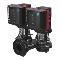
• On twin-head pumps, the duty and standby
pumps must be alternated on a regular basis, that
is once a week, to ensure an even distribution of
the operating hours on both pumps. Pump change
can be effected either manually or automatically
by installing a suitable pump controller.
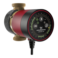
• If twin-head pumps are used for hot water
recirculation, the duty and standby pumps must
be alternated on a regular basis, that is once a
day, to avoid blocking of the standby pump due to
deposits (calcareous deposits, etc.). We
recommend automatic pump change.
6. Handling and storing the product
6.1 Storing the product
The contractor must inspect the equipment on
delivery and make sure that it is stored in such a way
that corrosion and damage are avoided.
If you do not operate the pump soon after arrival,
store it in a clean, dry place with slow, moderate
changes in ambient temperature. Protect the pump
from moisture, dust, dirt and foreign bodies. Before
and during storage we recommend these
precautions:
1. Make sure that the bearings are filled with the
recommended grease to prevent moisture from
entering around the shaft.
2. Make sure that the inlet and outlet ports and all
other openings are covered with cardboard, wood
or masking tape to prevent foreign objects from
entering the pump.
3. Cover the unit with a tarpaulin or waterproof
material or other suitable covering if it is to be
stored where there is no protective covering.
4. Rotate the shaft two turns every two weeks to
prevent corrosion of the bearing surfaces and the
shaft seal faces due to moisture.
If more than six months will pass before the
equipment is put into operation, consider applying a
suitable corrosion inhibitor to the internal pump parts.
19
English (GB)