Introduction
Installation
1. Plug the power cord into the appropriate jack (R5) on the rear panel.
2. Plug the power cord from the Power Module into a line power (mains) outlet.
3. Plug the earphones into the earphone jacks on the rear panel. R3 is for the right and R4 is
for the left earphone/insert phone.
4. Turn the power switch to ON (R6).
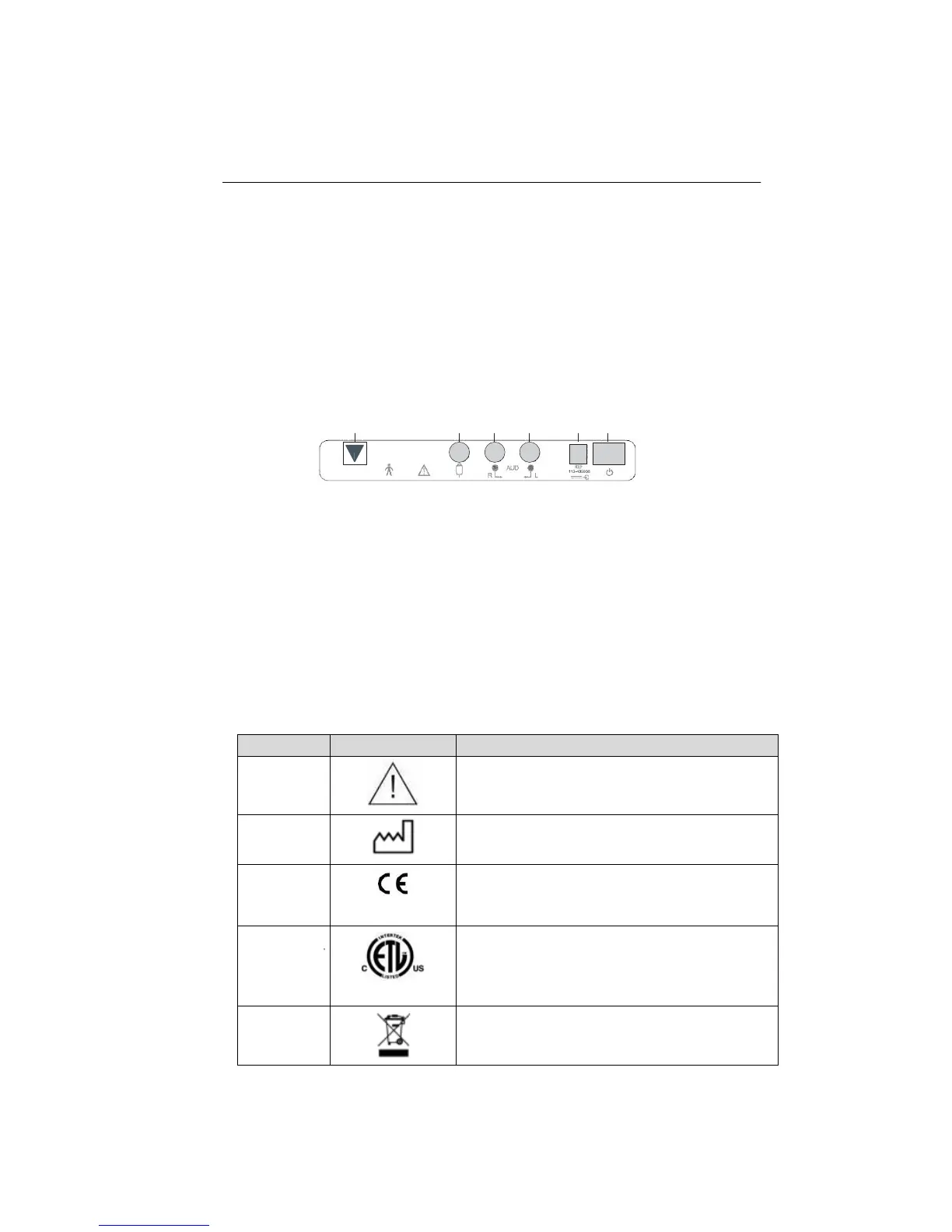
Rear panel connectors
R1 R2 R3 R4 R5 R6
Figure 1: Rear panel connectors.
R1 -Covered by a sticker and intended for service personnel only.
R2 -Patient Hand Switch input jack (standard phone jack).
R3 -Right ear phone output jacks (standard phone plug). Insert either DD45
Headphone or Insert Earphone jacks.
R4 -Left earphone output jacks (standard phone jack). Insert either DD45
Headphones or Insert Earphone plugs.
R5 -Power Input jack (2.1 mm pin).
R6 - Power switch.
Table of symbols on the GSI 18
1-3 1718-0100 Rev. E
1
Attention, consult accompanying documents.
2
Date of manufacture.
3
0344
CE Marked in accordance with the European
Council Directive 93/42/EEC concerning medical
devices.
4
3145885
Medical device listing mark for U.S. and Canada
by Intertek Testing Service.
5
Special Recycling Required. Do not dispose in
landfill.