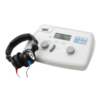
Introduction
F6
– Selects the DD45 calibration file for transducers
.
When the
button is
pressed, the display will flash
.
Press the
button again to engage the
TDH 39
Transducer.
The symbol is shown on the right side of the display when selected.
F7
- Selects insert earphone calibration file for transducers
.
When the
button
is pressed, the display will flash
. P
ress the
button again to engage the insert
transducers
.
The symbol
is shown on the right side of the display when selected.
F8
- Control for setting the stimulus frequency
.
Frequency is indicated in the bottom
center of the display.
F9
- Select to present the stimulus to the Left ear
.
An “
L
” will appear in the lower
right side of the display to indicate the stimulus is being routed to the left ear.
F10
-Present bar for stimulus presentation
.
The symbol
appears on the left side of
the display when the stimulus is being presented.
F11
-Select to present the stimulus to the Right ear
.
An “
R
” will appear in the lower
left side of the displa
y to indicate the stimulus is being routed to the right ear.
F12
-Hearing Level knob for setting the stimulus intensity level
.
Level is indicated on
the center top of the display.
NOTE:
The above symbol is located on the rear panel of the GSI 18 and denotes a
Type B applied part.
1718-0100 Rev. E 1-7