0MNMPMK10NPENUB 00 Pag. 33 / 57
3.11 Components of the block diagrams
The UPS is made up of the following sub-assemblies:
RECTIFIER
This represents the input stage and its function is to convert the alternating voltage of the power supply line into
direct voltage.
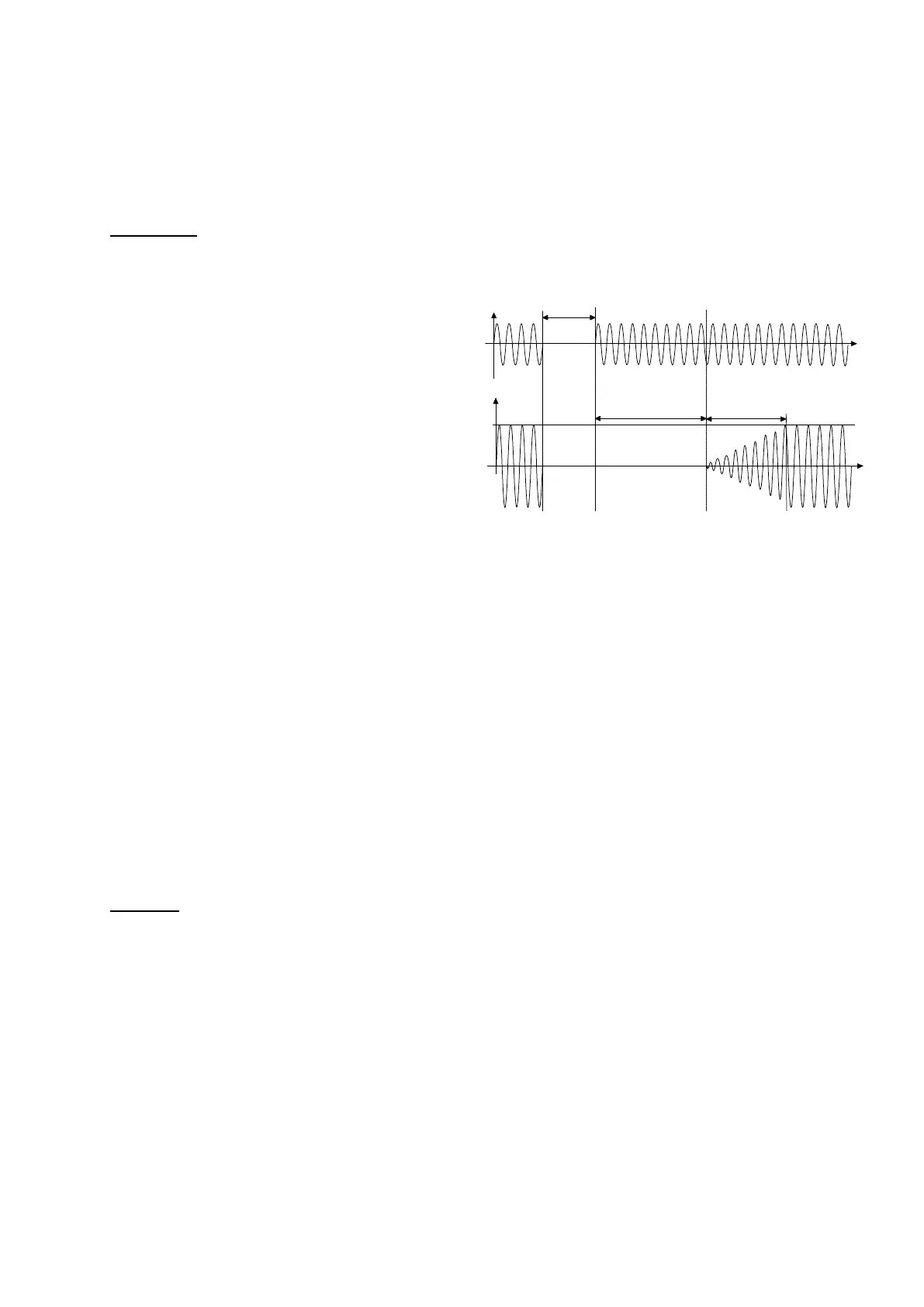
Rectifier start-up can be programmed from the
display panel. The following in particular can be
set:
The delay in start-up t0 –t1 (this allows a non
simultaneous start-up of several UPSs connected
to the same mains);
The time for the start-up, t1–t2 (this avoids
oversizing any generator that may be located at
the UPS input).
The rectifier carries out the following functions:
- feeds the inverter with direct
voltage;
- automatically charges the
battery;
- optimizes the input power factor by means of an automatic charging system.
The system for the cyclical recharging of the battery has two phases.
The first phase consists in recharging the battery with limited current and increasing voltage (up to the preset charge
value “Vb_max”). This phase is maintained until the battery is fully charged (Batt=100%Ah), which is detected by
measuring the current entering the battery.
In the second phase, with the battery fully charged, the battery charger is deactivated so as to remove any residual
current in the battery in order to lengthen its lifespan and to prepare the rectifier for the optimization of the input
power factor.
A cycle is also automatically effected to check the state of charge and to reintegrate the normal battery auto
discharge.
BATTERY
This is the energy reserve to power the load when power is no longer supplied to the UPS. It is housed in one or
more additional cabinets. The battery cabinet must be provided with a sectioning device and a protection device
(magneto-thermal switch or disconnector with fuses).
The load is powered with the energy accumulated in the battery when there is no MAINS present (black out), or
when the mains goes outside the acceptance field (frequency or voltage). In this phase of operation the energy
required by the equipment connected to the UPS output is supplied by the battery, which has previously been
charged. The alphanumeric PANEL at the front of the UPS shows the expected residual BACKUP TIME, calculated
according to the power supplied and the state of charge of the batteries. The value provided is merely indicative,
since the power required by the connected load may change during discharging. The backup time can be increased
by disconnecting some of the connected equipment. When the remaining backup time goes lower than the value
preset as the END OF BACKUP TIME PRE-ALARM (factory-set at 5 minutes), the buzzer increases the sound
frequency while the yellow BATTERY LED starts flashing; in these conditions it is advisable to save any work in
progress. After this time the UPS will interrupt the power supply to the loads.
When the MAINS is restored, the UPS automatically restarts and starts recharging the batteries.
input
current
t
input
voltage
t
black out
t
t
0 1
t
2
setting
setting