17.7.17
Elektropneumatic positioner DigiPos
4. Design of the positioner
14
4 . 3 Electrical connections
Tab. 2 Electrical connections
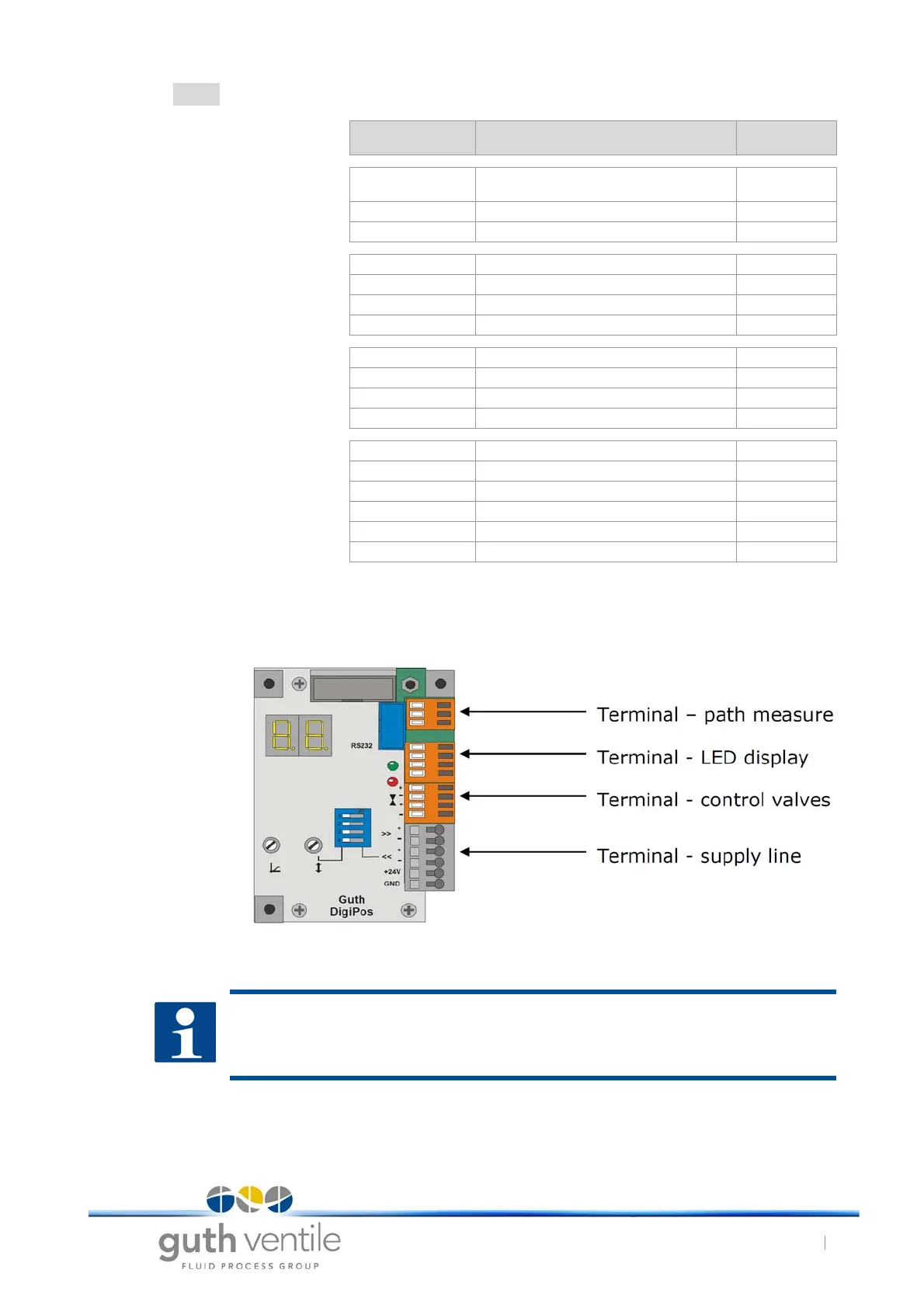
Fig. 8 Electrical connections; Positioner circuuit board
Type Designation Conductor col-
our
Path measure-
ment
Output Voltage output +24V DC brown (circular
sensor)
Input Sensor Input +10V DC black
Input Sensor Ground blue
Display
LEDs
Output Green LED, anode (+) red
Output Green LED, cathode (-) black
Output Red LED, anode (+) red
Output Red LED, cathode (-) black
Control valves Output Supply air (+) red
Output Supply air (-) black
Output Vent air (+) red
Output Vent air (-) black
Supply line Output Position signal, 4-20 mA (+)
Output Position signal, 4-20 mA (-)
Input Setpoint 4-20 mA (+)
Input Setpoint 4-20 mA (-)
Supply +24V DC
Supply Ground
NOTICE
• The path measurement, LED display and control valve terminals are already connected at the
works. The supply line terminal must be connected in the system.