17.7.17
Elektropneumatic positioner DigiPos
4. Design of the positioner
17
4 . 4 Principle of operation
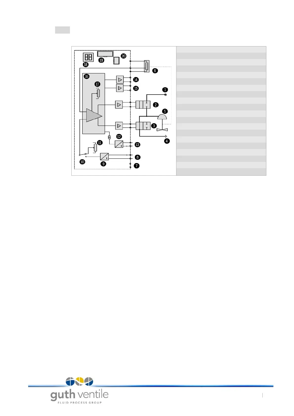
Tab. 4 Block diagram
With a periodical path measurement (6) the microprocessor (16) determines the current position of the pneu-
matic actuator (5). The target position of the actuator is specified with a setpoint signal (8) or optionally the inter-
nal setpoint potentiometer (11). If, for example, the current position is lower than the setpoint, the supply air valve
(2) is opened and the actuating pressure in the pneumatic actuator (5) increased. This then moves to the open
position until the setpoint is reached. If the current position is too high, the actuating pressure is lowered with
the vent valve (3) (depressurisation). The control valve then moves towards the closed position until the setpoint
is reached. The switching valves (2 and 3) are then permanently open. For slight changes in the path the switch-
ing valves (2 and 3) are activated with short pulses. When the setpoint is reached both switching valves (2 and
3) are closed. The positioner therefore does not consume any air itself in the adjusted state. Compressed air is
therefore only used for opening the actuator. The current position is shown on the display (18) and indicated by
the current output of the position signalling unit (13). The position is shown as a percentage and is based on the
full stroke of the valve.
Fig. 14 Block diagram
1 Supply air
2 Supply air solenoid valve
3 Vent air solenoid valve
4 Vent air
5 Pneumatic actuator
6 Path measurement
7 Supply voltage
8 Setpoint 4-20 mA
9 Current input
10 Setpoint switchover
11 Potentiometer; internal setpoint
12 Current output stage
13 Position signalling
14 Green LED
15 Red LED
16 Mikroprocessor
17 Potentiometer; Control accuracy
18 Position indication
19 Extension connector
20 RS232 interface