17.7.17
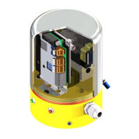
Elektropneumatic positioner DigiPos
List of contents
2
Availability and Completeness
These operating instructions constitute part of the valve delivery and must be kept available so that they can be referred to by authorised personnel
at any time. No sections may be removed from these instructions. Should the operating instructions or individual pages be missing, they must be
replaced at once.
Change Service
This documentation is subject to the Change Service of Guth Ventiltechnik GmbH.
Changes may be made to this documentation without notice of such changes being
given.
Copyright
This documentation contains information that is protected by copyright. It may only be
used in connection with the use of the valve.
List of contents ....................................................................................................................... 2
1. General information................................................................................................................. 3
1.1 Information for your safety ........................................................................................... 3
1.2 Marking of security instructions in the operating manual ............................................. 3
1.3 Designated use ............................................................................................................ 3
1.4 Personnel..................................................................................................................... 3
1.5 Modifications, spare parts, accessories ....................................................................... 3
1.6 General instructions ..................................................................................................... 3
2. Safety instructions ................................................................................................................... 4
2.1 Intended use ................................................................................................................ 4
2.2 Notes on the guarantee ............................................................................................... 4
2.3 Safety instructions........................................................................................................ 4
3. General information on the positioner ..................................................................................... 5
3.1 Basic functions............................................................................................................. 5
3.2 Extended settings via the RS232 interface .................................................................. 5
3.3 Mounting on diaphragm actuator ................................................................................. 6
3.4 Mounting on piston actuator......................................................................................... 7
3.5 Mounting on rotary actuator ......................................................................................... 8
4. Design of the positioner........................................................................................................... 9
4.1 Unit design of the various versions .............................................................................. 9
4.1.1 Unit design of DigiPos for diaphragm actuators........................................................... 9
4.1.2 Unit design of DigiPos for piston actuators ................................................................ 10
4.1.3 Unit design of DigiPos for rotary actuators................................................................. 11
4.1.4 Component table........................................................................................................ 12
4.2 Electrical and pneumatic connections........................................................................ 13
4.3 Electrical connections ................................................................................................ 14
4.3.1 Terminal - path measurement 15
4.3.2 Terminal - LED display.............................................................................................. 15
4.3.3 Terminal - control valves (solenoid valves)............................................................... 15
4.3.4 Terminal supply line ................................................................................................... 16
4.4 Principle of operation ................................................................................................. 17
5. Installation ............................................................................................................................. 18
5.1 Replacement of positioners mounted by Namur with DigiPos ................................... 18
5.2 Mounting on a diaphragm actuator ............................................................................ 19
5.3 Mounting on piston and rotary actuator ..................................................................... 20
5.4 Connection of the electric lines .................................................................................. 21
5.5 Connection of th pneumatic lines............................................................................... 21
5.6 Installation recommendations .................................................................................... 21
6. Commissioning...................................................................................................................... 22
6.1 Operation ................................................................................................................... 22
6.2 Zero point setting and stroke alignment .................................................................... 22
6.3 Positioner accuracy.................................................................................................... 23
6.4 Software Programming/Characteristic Curve Adjustment.......................................... 23
6.5 Maintenance and Care............................................................................................... 23
6.6 Faults ......................................................................................................................... 23
6.6.1 Electronic error codes ................................................................................................ 23
6.6.2 Other faults ................................................................................................................ 23
7. Technical Data ...................................................................................................................... 24
7.1 Mechanical Data ........................................................................................................ 24
7.2 Pneumatic Data ......................................................................................................... 24
7.3 Elektric Data............................................................................................................... 25
8. Type key................................................................................................................................ 26
List of contents
Guth Ventiltechnik GmbH
Im Niedersand 52
D - 76877 Offenbach an der Queich
+49 (0) 6348 23 801 - 0 Fax: +49 (0) 6348 23 801 - 85
www.guth-vt.de sales@guth-vt.de