EasyManuals Logo

GW Instek GPE-1326 Series User Manual

GW Instek GPE-1326 Series
50 pages
To Next Page IconTo Next Page
To Previous Page IconTo Previous Page
Page #31 background imageLoading...
Page #31 background image
SETUP
31
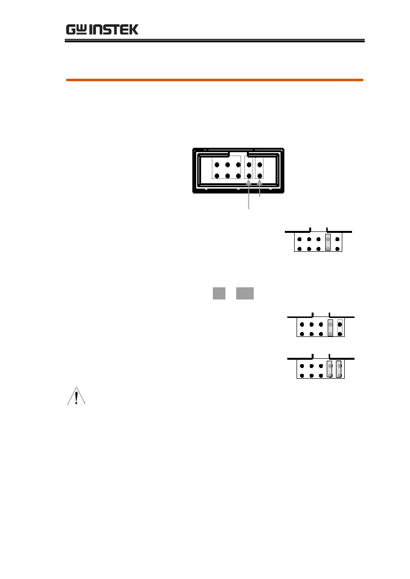
Remote Control Setting
Background /
Connection
Through the "Remote Control" terminal, the GPE-
1326/2323/3323/4323 series can turn the power on
or off.
 
Panel operation
1. Short pins 7 and 8 (remote
control setting). This will put
the power state (ON/OFF)
under remote control. At this
moment, the On / OFF icon
flashes on the LCD display.
2. Output control :
Pin 9 & 10 Open: ON state.
Pin 9 & 10 Short: OFF state.
Warring
The remote control terminal can only be controlled
by shorting (external relay or jumper shunt)
/opening the pins. Voltage cannot be applied to
the pins. It is strictly prohibited to short pins 5 & 7
or 6 & 8. Pin 1~6 must be set to open.
ON/OFF setting
Remote control setting
1 3 5 7 9
2 4 6 8 10

Questions and Answers:

Question and Answer IconNeed help?

Do you have a question about the GW Instek GPE-1326 Series and is the answer not in the manual?

GW Instek GPE-1326 Series Specifications

General IconGeneral
BrandGW Instek
ModelGPE-1326 Series
CategoryPower Supply
LanguageEnglish

Related product manuals