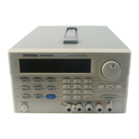
PSM-SERIES PROGRAMMABLE POWER SUPPLY
USER MANUAL
10
27.
FL DIMMER
Adjust the intensity of VFD. After pressing
[SHIFT], can press [FL DIMMER] continually
until the required brightness is reached. Then
press again the [SHIFT] to end the setting.
28.
Set beeper by pressing [SHIFT][
] to turn
ON/OFF the buzzer.
29.
OUTPUT Turn on or off output by pressing the knob.
30.
DISPLAY LIMIT
Switch over the voltage and current mode by
pressing [DISPLAY LIMIT].
The setting value will be displayed, press again
[DISPLAY LIMIT] or wait a few seconds to
return to the previous status.
4-2. Rear Panel brief
1. AC Power Socket
AC power input terminal.
2. AC Select Switch
Switch Voltage to 100V, 120V, 220V or 230V,
50/60Hz.
3. Cooling Fan
A cooling fan.
4. Interface
GPIB or RS-232 communication interface.
5. Output Terminal
The output terminals of rear panel connected
with case, including output sampling terminal
and ground terminal.
PSM-SERIES PROGRAMMABLE POWER SUPPLY
USER MANUAL
11
4-3. Display brief
1. Adrs
Set the power sup
ly to the address of Listen or
Talk by using the interface card.
2. Rmt Set the power supply to Remote Control mode.
3. ERROR
The Error message appears when the command
from the Remote Controlled Interface is in error.
4. SHIFT Select the second level function.
5. AUTO Set the power supply to Auto mode.
6.
8V, 15V, 20V,
30V, 60V
The output ranges of power supply.
7. OVP
When the indicator lights up without blinking,
means the OVP function is on. When the Over
Voltage Protection function is triggered, the
indicator will be changed to blinking status, and
the message “OVP TRIPPED” will be displayed.
Now clear the OVP function. When the light of
indicator is off, means the OVP function is off.
8. OCP
When the indicator lights up without blinking,
means the OCP function is on. When the Over
Current Protection function is triggered, the
indicator will be changed to blinking status, and
the message “OCP TRIPPED” will be displayed.
ow clear the OCP function. When the light of
indicator is off, means the OCP function is off.

 Loading...


