The turbidimeter has a built-in printer and an RS232 output for
connection to a printer, data logger or computer
and a recorder output.
The turbidimeter contains a real-time clock with battery. The clock
provides a time-date stamp on all data transmitted to the built-in printer
or to external devices by way of the RS232 interface (i.e., measurements
and calibration records).
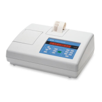
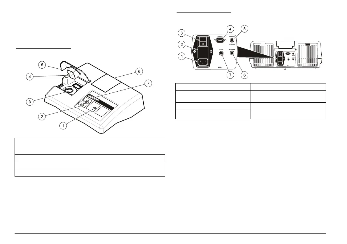
Figure 1 Front overview
1 Mode display: shows the calibration
standard number, setup number or
sample number
5 Cover for the sample cell
compartment
2 Keypad 6 Printer cover
3 Sample cell holder 7 Eight-digit LED display
4 Light shield
Figure 2 Back overview
1 Power cord connector 5 Air purge fitting
2 Fuse holder 6 Recorder output jack for a chart
recorder (0 to 1 V output)
3 Power switch 7 Remote cable jack for flow valve
module connection to the automatic
flow cell (low pressure)
4 DB9 connector for RS232 cable
Product components
Refer to Figure 3 to make sure that all components have been received.
If any of these items are missing or damaged, contact the manufacturer
or a sales representative immediately.
8 English
 Loading...