5. Push ENTER.
6. Push SETUP.
Configure the RS232 connection
1. Push SETUP. The SETUP light turns on.
2. Use the arrow keys to select an option:
Option Description
10 Sets the baud rate (default=1200).
11 Sets the character length (default=8).
12 Sets the stop bit (default=1).
13 Sets the parity select (default=NONE).
3. Push ENTER.
4. Use the arrow keys to change the value.
5. Push ENTER.
6. Push SETUP.
Computer (RS232) commands
A communication program (i.e., such as Window Terminal or ProComm
Plus) is recommended for computer operation of the instrument.
Configure the communication program to the RS232 connection settings.
Refer to Configure the RS232 connection on page 37
.
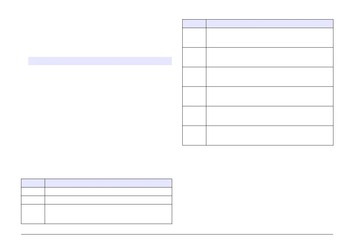
Table 5 shows the RS232 command set for the instrument.
Table 5 RS232 command set
Command Description
VAL Gets the current measurement with the measurement units.
LST Gets the calibration standards and coefficients.
DAT Gets the current date.
To change the date, enter DAT=MM/DD/YY (MM=month, DD=day,
YY=year), then push Enter.
Table 5 RS232 command set (continued)
Command Description
TIM Gets the current time in 24-hour format.
To change the time, enter TIM=HH:MM (HH=hour, MM=minutes),
then push Enter.
RMN Gets the recorder minimum value.
To change the recorder minimum value, enter RMN=XXXXX
(XXXXX=a number, minimum value=0), then push Enter.
RMX Gets the recorder maximum value.
To change the recorder maximum value, enter RMX=XXXXX
(XXXXX=a number, maximum value=10,000), then push Enter.
RTN Gets the recorder trim minimum value.
To change the recorder minimum value, enter RTN=XXXXX
(XXXXX=a number, minimum value=200), then push Enter.
RTX Gets the recorder trim maximum value.
To change the recorder maximum value, enter RTX=XXXX
(XXXX=a number, maximum value=4800), then push Enter.
SAV Gets the signal average buffer size.
To change the signal average buffer size, enter SAV=XX (XX=a
number, maximum value=15, default=10), then push Enter.
Connect to a data recorder
Note: Use a twisted-pair, shielded recorder cable. Use of non-shielded recorder
cable may result in radio wave emission levels greater than is allowed under the
compliance regulations listed.
Note: Connect the shield of the recorder cable to the recording device chassis
ground terminal to decrease the effects of unwanted interferences.
Connect a ¼–inch recorder phone plug to the recorder output jack on the
back of the instrument. Refer to Figure 2 on page
8. For the best
performance, use a twisted-pair, shielded recorder cable that is no more
than 1.8 m (6 ft) in length with a load impedance greater than 10 kohms.
English 37
 Loading...