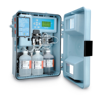
Figure 1 CA610 fluoride analyzer
1 Power switch 8 Keypad/Display
2 Power connections 9 Pinch plate with openings for half-cell electrodes
3 Network and 4–20 mA connections 10 Reagent bottles
4 Air purge, optional 11 Enclosure drain
5 Relay and alarm contact connections 12 Sample inlet
6 Customer access cover 13 Sample drain
7 BNC connectors and valves
Section 3 Installation
D A N G E R
Electrocution hazard. Always remove power to the instrument before making electrical connections.
D A N G E R
Multiple hazards. Only qualified personnel must conduct the tasks described in this section of the
document.
English 7