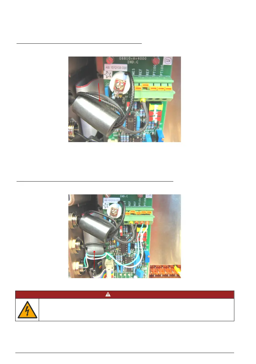
For the selective or combined electrode, install the cable gland and pass the cable of into the
electronic unit in the same way as for all other cables (as described in Connecting peripherals
on page 10). Once both wires (measurement and shield) are in place, pass them both through the
ferrite block. Make a loop by passing them through a second time before connecting them to their
respective inputs as illustrated in Figure 3.
Figure 3 Selective or combined electrode connection
For the reference electrode (not applicable in the case of a combined electrode) and the temperature
sensor, install the cable glands and pass the cables into the electronic unit in the same way as for all
other cables (as described in Connecting peripherals on page 10). Once the reference electrode wire
and the two temperature sensor wires are in place, pass them all through the second ferrite block.
Make a loop by passing them through a second time before connecting them to their respective
inputs as illustrated in Figure 4 (the temperature sensor has no polarity).
Figure 4 Reference electrode and temperature sensor connections
5.4.2 Mains power supply
D A N G E R
Electrocution hazard. Always remove power to the instrument before making electrical connections.
12 English
 Loading...


