80459-641-01E Model 6 Motor Control Centers
10/2012 Section 4—Installing the MCC
© 1999–2012 Schneider Electric All Rights Reserved
21
ENGLISH
5. Supporting the MCC by its base channels and/or lifting angles, lift it into
place. The front edges of the base channels must be aligned to form a
continuous front in a straight line. Use a chalk line, string or other
method to align the front base channels in a straight line.
6. Using the notches in the base channels, carefully move the sections in
to alignment with a crowbar (see Figure 9).
NOTE: Use caution when moving MCC sections, as they are top heavy.
See “Handling the MCC” on page 15 before moving the MCC.
Joining Corner Channels 1. Turn off all power supplying this equipment before working on or inside
the equipment, and follow lockout/tagout procedures. Always use a
properly rated voltage sensing device to confirm the power is off.
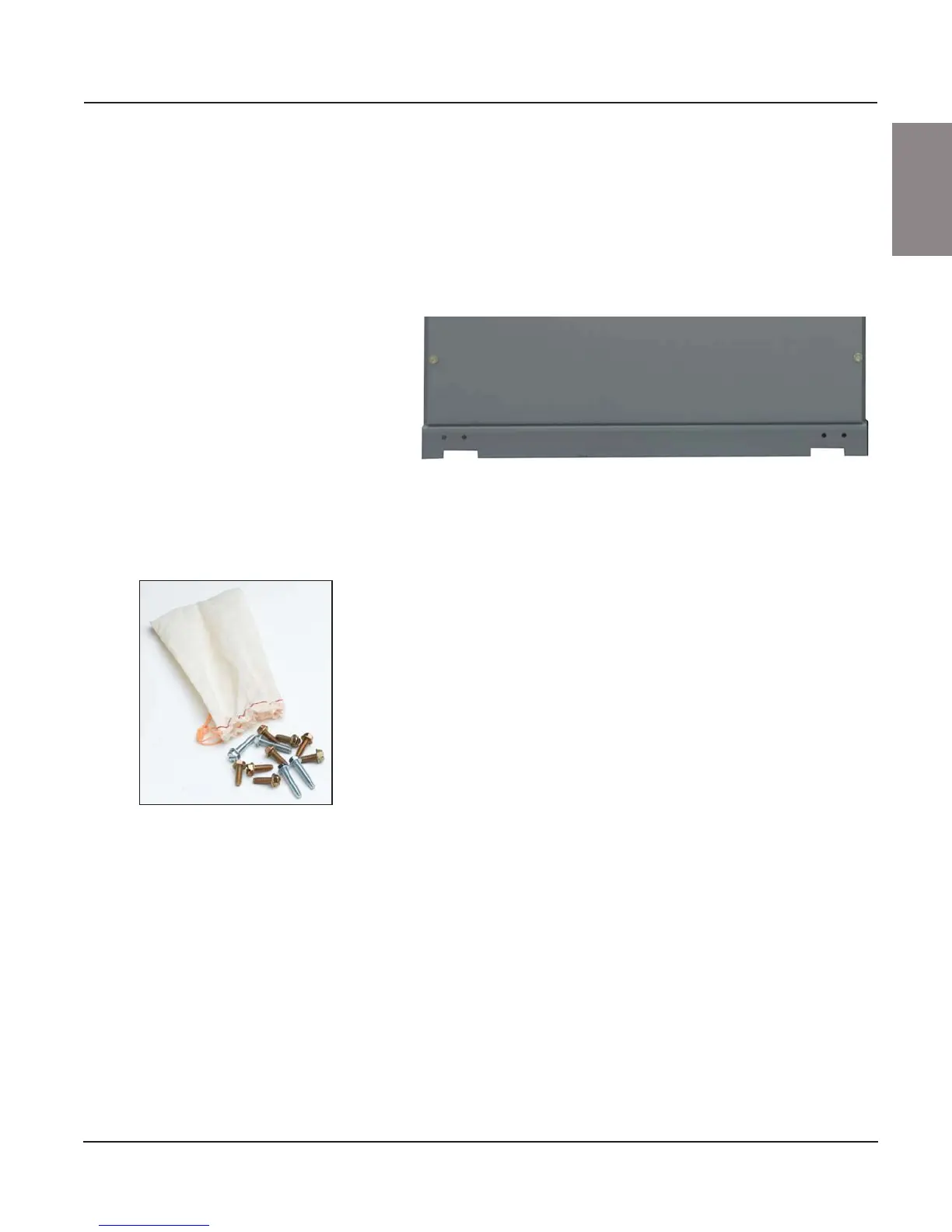
2. The hardware kit for joining sections (see Figure 10) is bagged and tied
to the right front corner channel of each shipping split.
3. Locate the four half-circle shaped notches on the inside surface of the
corner channels (see Figure 11A).
4. Using four of the 3/4 in. x 1/4-20 hex head thread-forming screws
supplied in the hardware kit, join the front vertical corner channels by
inserting the screws through the clearance holes located within the
half-circle shaped notches and into the mating thread-forming hole (see
Figure 11B).
NOTE: Insert the screws from whichever side provides the easiest
access to the holes; either side will allow proper joining of the channels.
5. Tighten the screws (see Figure 11C).
6. Repeat steps 3–5 to connect the rear corner channels.
NOTE: In some instances, holes in the rear channels will only be accessible
from the rear of the MCC with the MCC back plates removed. If the MCC is
not rear accessible, install as many screws as possible from the front of the
MCC (typically via the vertical wireway).
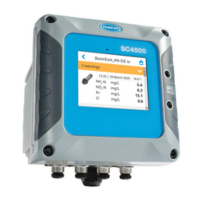
Figure 9: Base Channel Notches
Figure 10: Hardware Kit

 Loading...