80459-641-01E Model 6 Motor Control Centers
10/2012 Section 4—Installing the MCC
© 1999–2012 Schneider Electric All Rights Reserved
27
ENGLISH
Securing Structures to Wall—Seismic
Hazard
1
Designated Locations
When specified or required for the application (all seismic hazard areas with
S
s
in excess of 2.67g), each section must be laterally braced at the top
(bracing supplied by others) and connected to the load-bearing path of the
building system per detail supplied by engineer of record. Refer to the current
International Building Code or NFPA 5000 for location specific values of S
s
.
Remove the lifting angle and fasten each section to the lateral restraint
system using the same attachment points used to secure the lifting angle.
Re-use bolts [3/8 (.375 in.) by 7/8 (.875 in.) long #16 thread] and lock
washer (.094 in. thick) supplied with the lifting angle or hardware supplied
by others as appropriate. Pay particular attention to the limitation on the
depth the bolt can penetrate below the surface of the top plate. The bolts
must not penetrate the top plate of the enclosure by more than 0.50 in.
NOTE: On arc-rated MCCs, do not block roof flaps with lateral restraint
components.
1
Seismic hazard for site specific locations as defined by the current edition of the International Building Code or NFPA 5000 or relevant local building code or
consulting engineer of record.
DANGER
HAZARD OF ELECTRIC SHOCK, EXPLOSION, OR ARC FLASH
• Turn off power supplying equipment before installing lateral bracing.
• Bolts must not penetrate top plate by more than 0.50 in.
Failure to follow this instruction will result in death or serious injury.
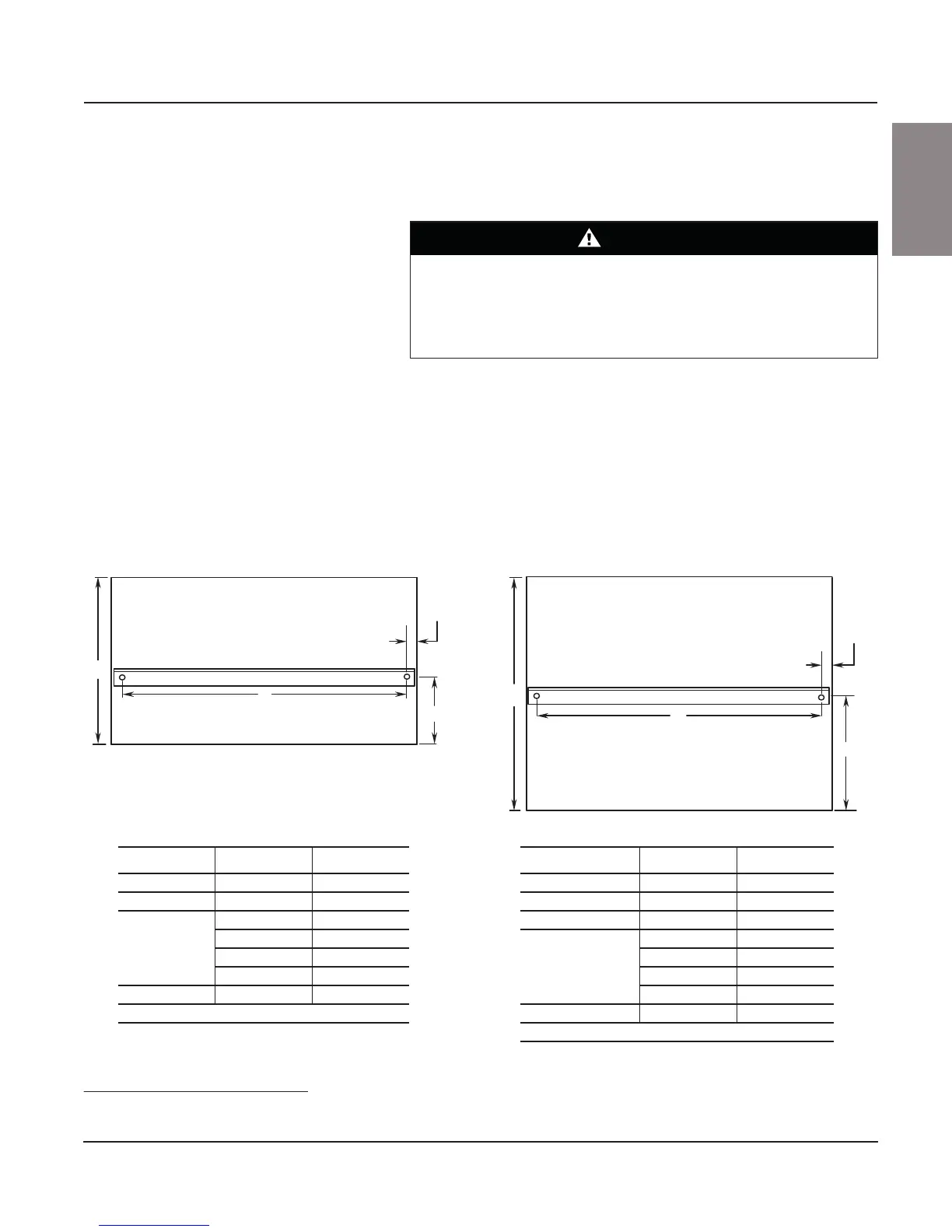
Figure 17: Attachment Locations for Top Lateral Bracing
C
B
A
A
B
C
D
(typ.)
D
(typ.)
Rear of MCC
Rear of MCC
15 in. (381 mm) Section Dimensions
Letter Section Width Dimension
A N/A 5.25 in. (133 mm)
B N/A 15.00 in. (381 mm)
C
20.00 in. (508 mm) 18.40 in. (467 mm)
25.00 in. (635 mm) 23.40 in. (594 mm)
30.00 in. (762 mm) 28.40 in. (721 mm)
35.00 in. (889 mm) 33.40 in. (848 mm)
D N/A 0.80 in. (20 mm)
N/A = Not applicable
20 in. (508 mm) Section Dimensions
Letter Section Width Dimension
A (single lifting angle) N/A 10.25 in. (260 mm)
A (two lifting angles) N/A 1.91 in. (48 mm)
B N/A 20.00 in. (508 mm)
C
20.00 in. (508 mm) 18.40 in. (467 mm)
25.00 in. (635 mm) 23.40 in. (594 mm)
30.00 in. (762 mm) 28.40 in. (721 mm)
35.00 in. (889 mm) 33.40 in. (848 mm)
D N/A 0.80 in. (20 mm)
N/A = Not applicable
NOTE: The dimensions shown are for locating top lateral bracing locations within individual MCC sections.
Refer to factory supplied drawings to determine appropriate anchor locations for the top lateral brace support system.

 Loading...