First Edition: March 31, 2007
2-4 Voltage Application Check (FX-951/FH-200)
4. Pressing [*] confirms the indication, and the “Low Temperature Alarm Tolerance
Setting” is indicated.
• Indicator [Left] flashes. Press [UP] and [DOWN] to check that the indication changes
within the input range.
NOTE Every time [*] is pressed, the indication will be determined and the flashing
indicator will be shifted from [Center] to [Right].
5. Pressing [*] accepts the indicated setting and proceeds to the “Supervisor/operator
Control Setting”.
• Check that pressing [UP] or [DOWN] changes the indication alternately as follows:
6. Pressing [*] finishes the parameter setting and returns the unit to the normal
operation.
If the unit does not operate correctly:
The P.W.B. is faulty. Check the P.W.B. using the procedure in step (7).
NOTE Perform the following inspection if the unit does not operate in steps (1) to (6).
(7) Visually inspect the reverse side of the P.W.B. (for control/connector) for faulty soldering
or pattern exfoliation.
If a faulty portion is found:
Correct soldering.
If a pattern coming off is found:
Replace the whole P.W.B.
CAUTION
If a fault is not found visually, replace the whole P.W.B. (for control/connector).
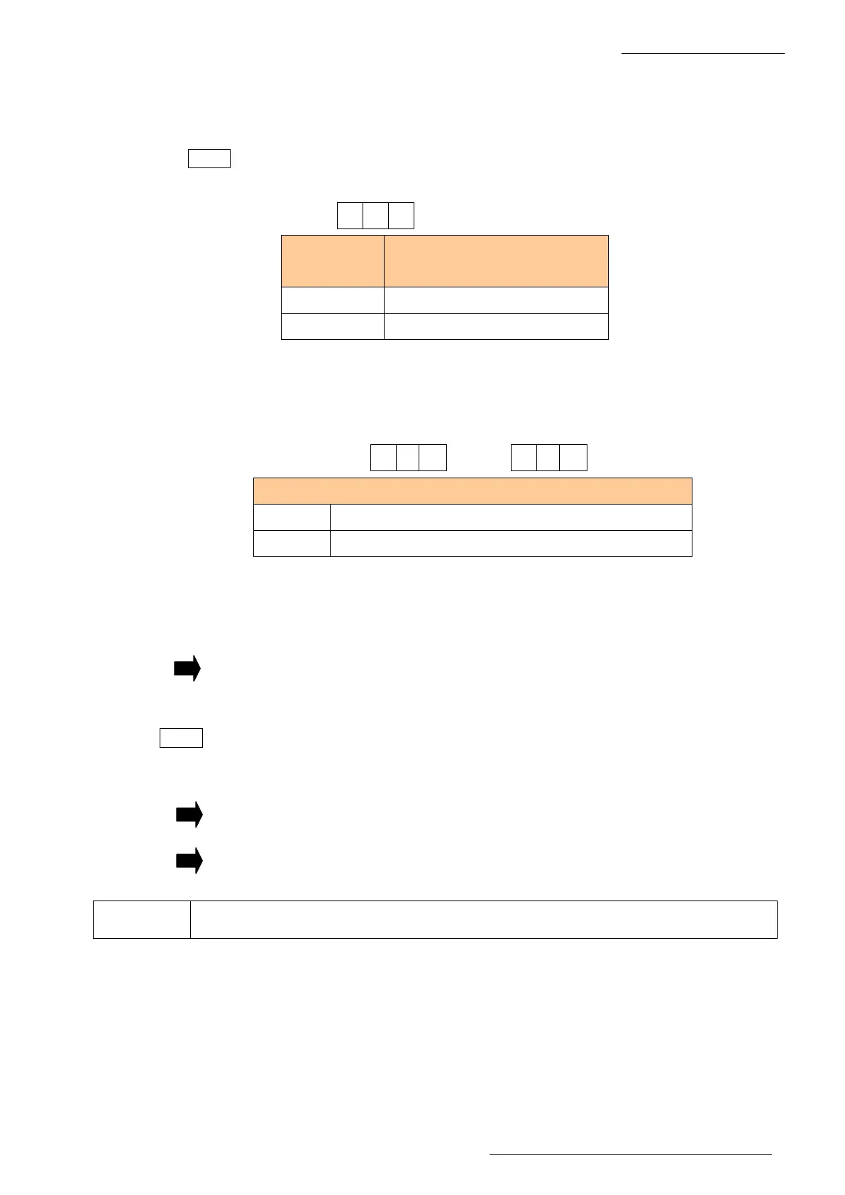
1 5 0
(Example of indicating 150°C)
Temperature
indication
Input range of low temperature
alarm setting
°C 30 to 150
°F 50 to 300
4 0
4 1
Supervisor/operator control setting”.
0 Card is required for offset value entry
1 Offset value entry is allowed without card
 Loading...