First Edition: March 31, 2007
4-2 P.W.B. (for Control/Connector) and Front Panel (FX-951/FH-200)
4-2 P.W.B. (for Control/Connector) and Front Panel
(1) Follow the procedures 4-1.
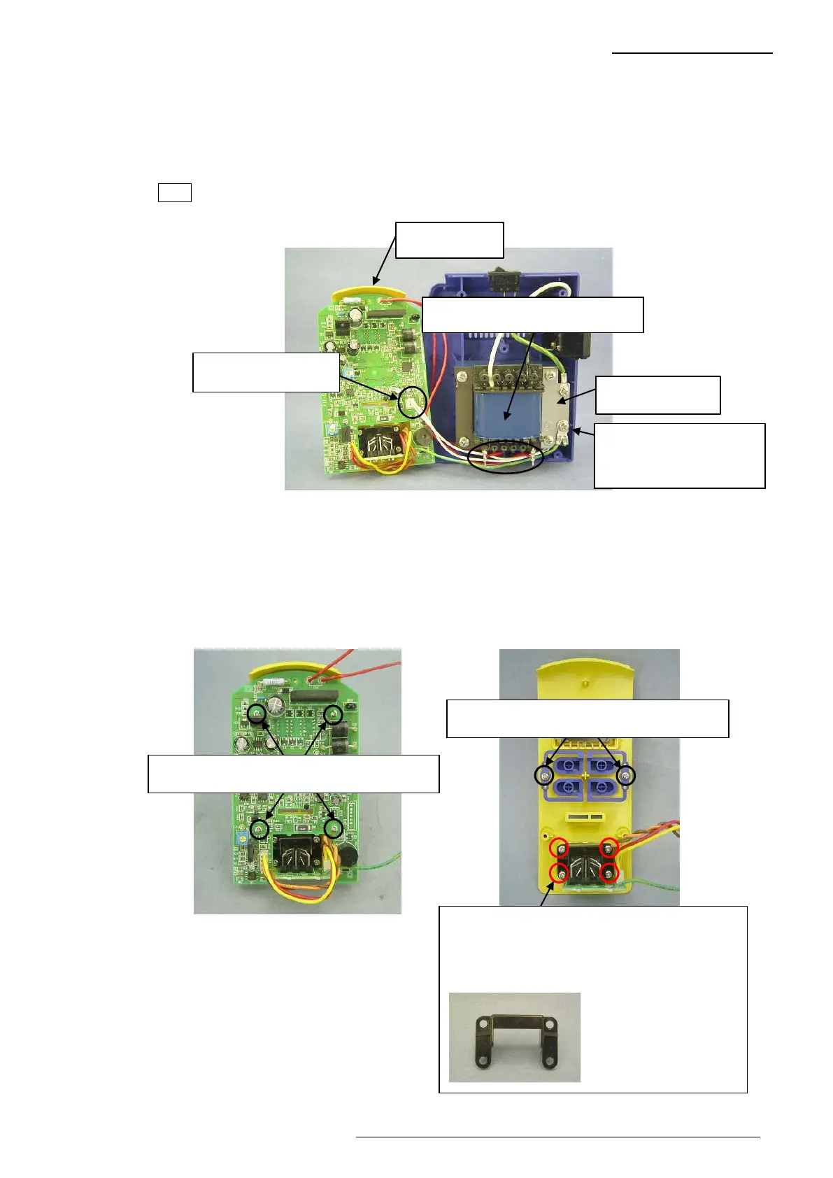
(2) Disconnect the connector for jack from the P.W.B. (4-2-1)
(3) Desolder 2 soldered sections at the secondary side of the transformer. (Fig. 4-2-1)
(4) Disconnect the grounding wire for P.W.B from the grounding plate. (Fig. 4-2-1)
Note The grounding wire for P.W.B. is attached together with the grounding wire for jack.
(5) Remove 4 screws and then disconnect the P.W.B. for control from the front panel. (Fig. 4-2-2)
(6) Remove 4 screws and then disconnect the P.W.B. for connector and holder from the front
panel. (Fig. 4-2-3)
(7) Remove 2 screws and disconnect the buttons R and L. (Fig. 4-2-3)
Four screws securing the P.W.B. for control
Fig. 4-2-2
Fig. 4-2-1
Secondary side of transformer
Grounding plate
Front panel
The grounding wires for
P.W.B. and jack are
attached together.
Connector for jack
Fig. 4-2-3
Two screws securing the buttons R and L
Four screws securing the P.W.B. for connector
Reference photo
If the 4 screws are
removed, the holder in
the photo at left will be
removed.
 Loading...