23
25
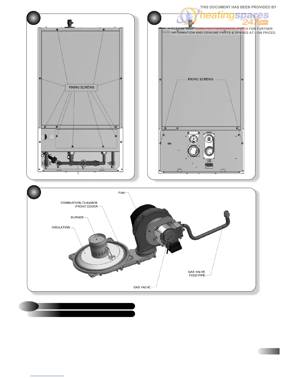
BURNER ASSEMBLY
6.2
GAS CONTROL VALVE, FAN &
Refer to Figures 22, 23, 24, and 25
a)
Remove the casing front panel, (2 screws) and lift off.
b) Lower the controls panel (2 screws).
c) Remove the sealed chamber front panel (7 screws).
d) Disconnect the ignitor plug, earth lead and detection plug
from the ignitor and detection electrodes.
e) Unscrew the screw holding the gas valve lead plug, and
disconnect the plug.
f) Disconnect the electrical leads from the fan (2 plugs).
g) Remove the base panel (1 screw).
h) Undo the nut holding the gas valve feed pipe to the gas
isolating cock, and disconnect.
i) Disengage the gas valve feed pipe grommet from the
casing by pushing it up.
23 24