36
8
47
Note: It is likely that there will still be some water spillage when the Hydroblock is removed.
Refer to Figures 18 & 22
a)
Ensure supply voltage is isolated.
b) Drain down the appliance; refer to section 9.24.
c) Undo the nut securing the discharge tail pipe to the pressure relief
valve and remove. Undo the nut securing the pressure gauge capillary,
and remove.
d) Undo the nut securing the pressure relief valve to the CH flow pipe
and remove the pressure relief valve.
e) Fit the replacement pressure relief valve, using new fibre washers.
f) Re-assemble in reverse order; ensure that all joints and seals are
correctly re-fitted.
i) Open the isolating cocks and vent air from the system using the
manual air vent. Re-pressurise the system as necessary and check for
water leaks.
Note: the pressure relief valve should not be used to
drain the system.
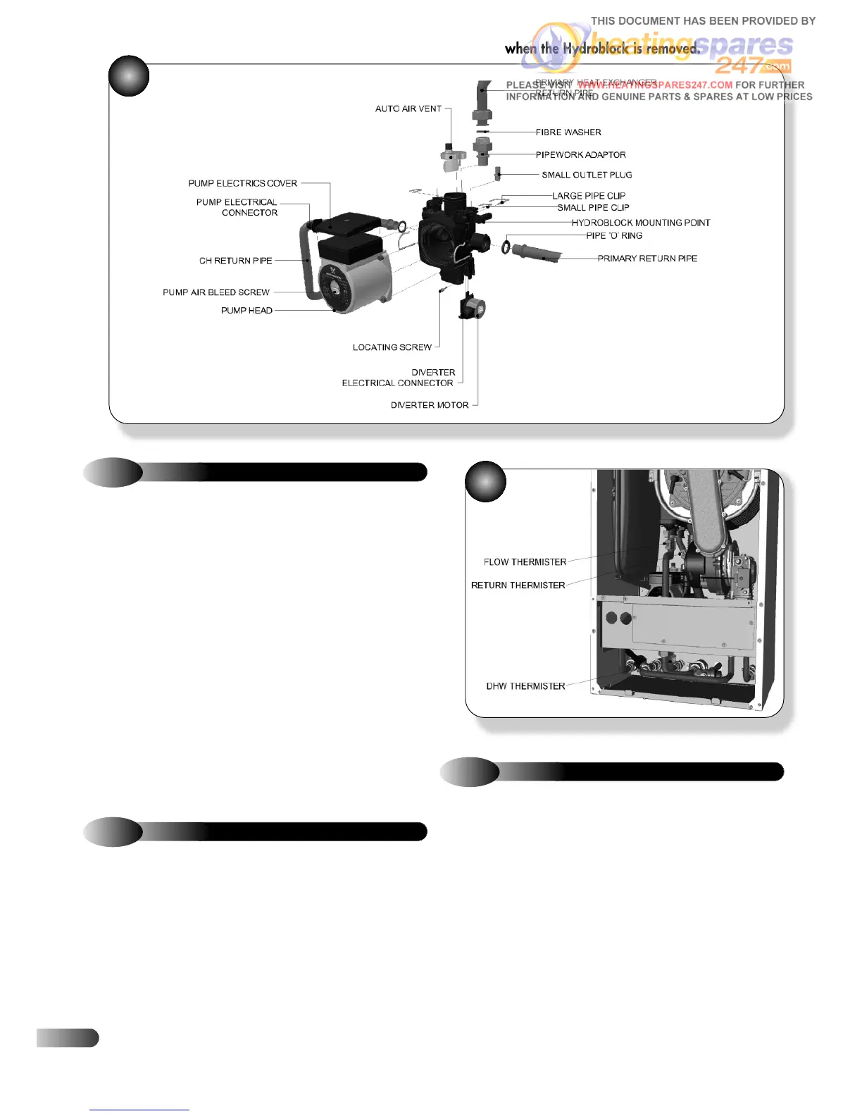
9.13
PRESSURE RELIEF VALVE
Refer to Figure 48
a)
Ensure supply voltage is isolated.
b) Disconnect the electrical lead from the sensor to be changed.
c) Unclip the sensor from the pipe and remove.
d) Clip the replacement sensor onto the pipe and position as
shown in Figure 48.
e) Reconnect the electrical lead.
9.14
WATER TEMPERATURE SENSORS
48
Refer to Figure 49
a)
Ensure supply voltage is isolated.
b) Disconnect the electrical lead from the flue sensor.
c) Twist the flue sensor to release the bayonet connection and
remove from the heat exchanger.
d) Fit the replacement flue sensor and reconnect the electrical lead
(blue plug).
Note: the thermal fuse is not removable or a
serviceable item, should the heat exchanger
overheat then the thermal fuse will blow
(blocking code ‘5’) and the entire heat
exchanger will need replacing.
9.15
FLUE SENSOR
!