7
PART NO. 956080
2.7
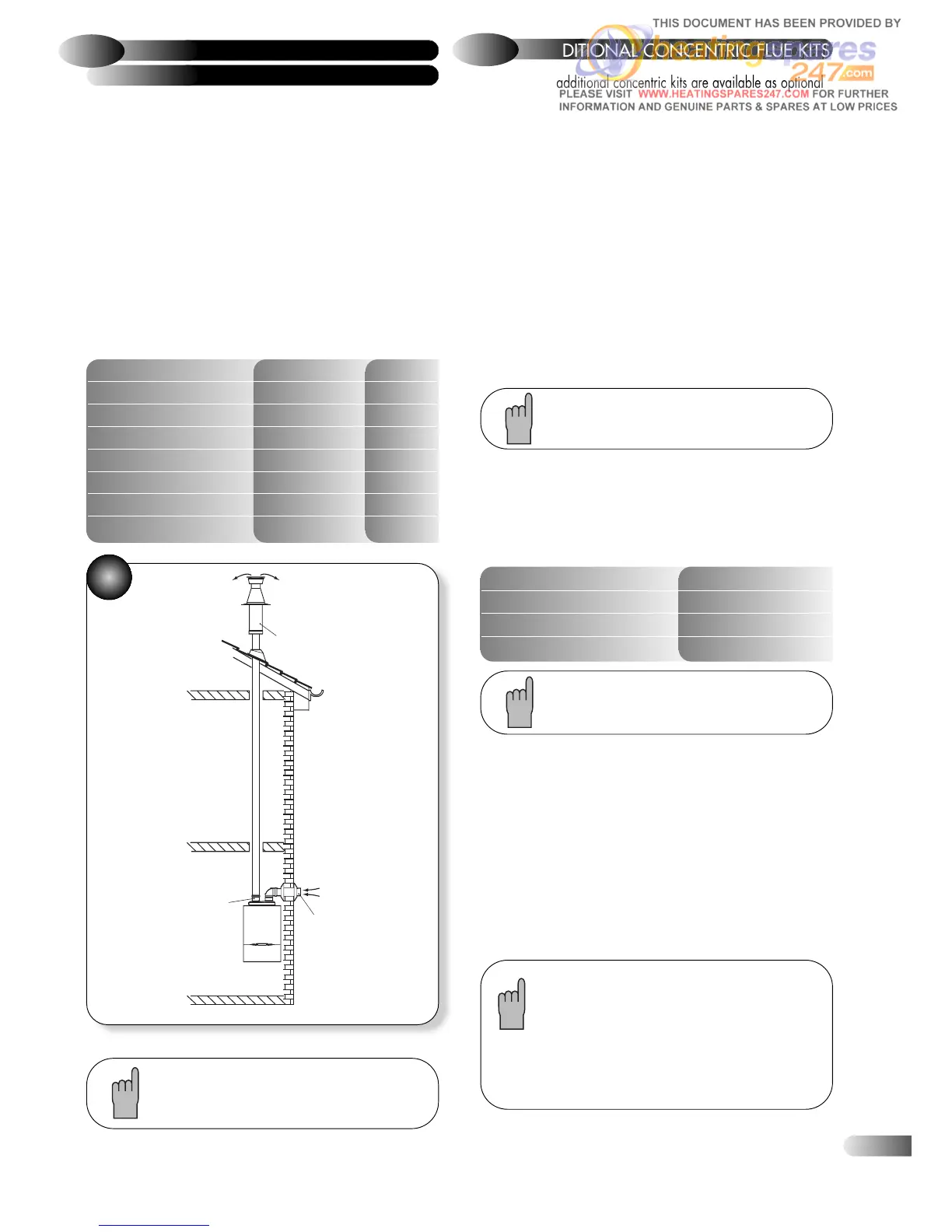
KIT F: TWIN FLUE SYSTEM (C53) –
This flue system kit is designed for installations where the air intake position is
different than the flue duct exit point. The kit comprises of a twin adaptor
from which the air intake is taken from the adjacent outside wall (see
example Figure 3g) and the flue duct is routed vertically through the roof.
It has to be noted that the flue duct is under pressure when the appliance is
in operation and the duct can leak poisonous carbon monoxide if the duct
components are not correctly assembled. It is
not recommended to route the
flue duct through living space areas, i.e. bed rooms, living rooms etc.
For installation details refer to the instructions provided with the twin flued kit.
Maximum flue resistance permitted for a twin flued
system = 75 Pa
Minimum flue resistance permitted for a twin flued
system = 18 Pa
Flue Component Flue Resistance (Pa) Part Number
Twin Flue Adaptor (required) 9.5 -
Air Inlet Terminal (required) 3 -
Flue Outlet Terminal (required) 1 -
80 mm dia straight duct 1 metre 1 956101
80 mm dia straight duct 2 metre 2 956102
90° Elbow (80/80) 8 956100
45° Elbow (80/80) 4 956099
3g
A flue system can be built up from the components
detailed in the table, but the total flue resistance must
not exceed the maximum stated.
!
!
The following additional concentric kits are available as optional
extras.
Flue Extension Ducts - 1000 mm and 500 mm long, (each
duct extends the flue length by up to 950 mm and 450 mm
respectively).
93° Extension Elbow - Allows an additional bend in the flue,
and has an 'equivalent length' of 1550 mm. This elbow is
mechanically different from the flanged elbow supplied as
standard with the appliance, but has the same equivalent length.
45° Extension Elbow - Allows an additional bend in the flue
and has an 'equivalent length' of 775 mm.
Vertical Turret Socket - For use with elevated horizontal flues
and vertical terminals.
Vertical Roof Terminal - For use where an external wall is not
available, or where it is desirable to route the ducts vertically.
For installation details refer to the instructions
provided with the individual flue kits.
The 'equivalent' flue length must not exceed the
maximum values stated.
These optional kits may be used with the standard flue kits to
produce an extensive range of flue options, providing that the
following rules are strictly obeyed.
a) The maximum/minimum permissible length of the room sealed
flue system are:
Horizontal flue terminal (all orientations) maximum 5000 mm (197 in)
Horizontal flue terminal (rear exit) minimum 250 mm (10 in)
Vertical flue terminal maximum 12000 mm (472 in)
Vertical flue terminal minimum 600 mm (23
1
/2 in)
2.8
ADDITIONAL CONCENTRIC FLUE KITS
Refer to Figures 2 and 3 to determine which option
kits are required before commencing the installation.
Instructions for installing the appliance with a
horizontal flue and straight extension ducts are
included in the main text of these instructions
(section 4.8).
b) The standard terminal must always be fitted horizontally;
horizontal ducts must have a continuous fall towards the
appliance of 2.5°. This ensures condensate runs back into the
appliance from the flue system. The vertical terminal must always
be used if a vertical outlet is required.
c) The concentric flue system must use either a flanged elbow or
a vertical flue turret socket at the entry/exit to the appliance.
d) All joints must be correctly made and secured in accordance
with the installation instructions. When cutting ducts, avoid swarf,
uneven and sharp edges to maintain duct integrity.