38
8
51
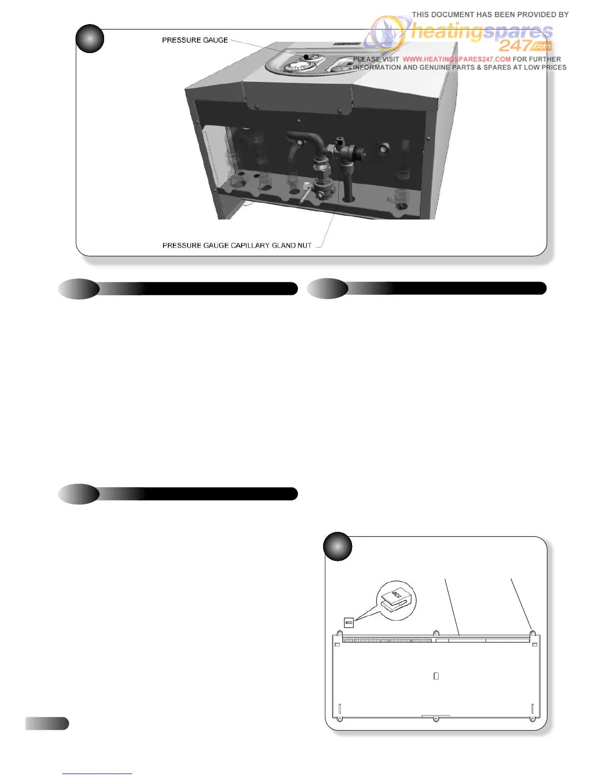
9.18
PRESSURE GAUGE
Refer to Figure 51
a)
Ensure supply voltage is isolated.
b) Drain down the appliance; refer to section 9.24.
c) Disconnect the pressure gauge capillary gland nut from the
pressure relief valve.
d) Having removed the decorative front and lowered the control
fascia disengage the pressure gauge from the fascia panel, and
remove the gauge.
e) Fit the new pressure gauge and re-assemble in reverse order.
f) Open the isolating cocks and vent air from the system using the
manual air vent. Re-pressurise the system as necessary and check for
water leaks.
9.19
AUTO AIR VENT
Refer to Figure 47
a)
Ensure supply voltage is isolated.
b) Drain down the appliance; refer to section 9.24.
c) Disconnect the vent tube from the auto air vent and check that it
is free from blockage.
d) Unscrew the auto air vent, and fit replacement.
e) Re-assemble in reverse order; ensure that all joints and seals are
correctly re-fitted.
f) Open the isolating cocks and vent air from the system using the
manual air vent. Re-pressurise the system as necessary and check for
water leaks.
9.20
CONTROL PCB
Refer to Figures 21, 29 & 52
a)
Ensure supply voltage is isolated.
b) Remove the casing front panel, unscrew and lower the control
fascia panel.
c) Unplug the electrical leads from the PCB. Refer to section 7.
d) Unplug the BCC if fitted.
e) Unscrew and remove the PCB plastic cover.
f) Unclip the user interface ribbon cable.
g) Unclip the PCB and withdraw.
h) Fit the new PCB and plug in the BCC if previously used.
i) Re-assemble in reverse order, ensuring user interface ribbon
cable is attached securely.
If the boiler requires resetting turn the control knob anti-clockwise to
'STANDBY' position and then back to 'ON' within two seconds.
Refer to section 5.4.
52
PCB HOUSING
BCC
Electrical
Connectors
Securing
Screws
•
•