9.3
GAS CONTROL VALVE
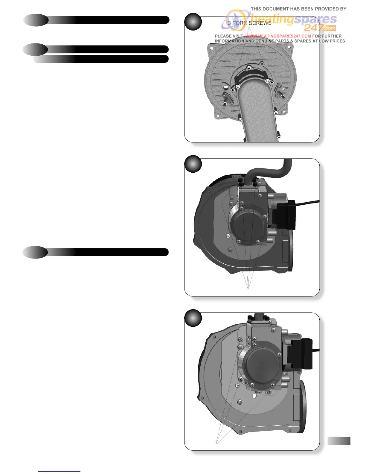
Refer to Figures 34, 35 & 36
a)
Remove casing and control panels as described in section 6.2.
b) Unscrew the gas valve electrical plug and disconnect from the
gas valve.
c) Ensuring the gas isolating cock is in the off position, undo the
union nut holding the gas valve feed pipe to the gas isolating
cock and disconnect.
d) Disengage the gas valve feed pipe grommet from the casing
by pushing it upwards.
e) Remove the three Torx screws (T-25) of the air/gas channel
fixing to the combustion chamber door (figure 34).
f) Remove the gas control valve, fan and air/gas channel as one
complete assembly by carefully pulling forward and rotating
anticlockwise. Then disengage the gas valve feed pipe from the
casing by lifting the assembly upwards.
g) With the assembly on a bench, unscrew and remove the four
screws securing the gas valve feed pipe, (figure 35).
h) Unscrew the three Torx screws (T-20) securing the gas valve
onto the fan (figure 36).
i) Replace the gas valve and re-assemble in reverse order.
j) Ensure all seals in particular the burner seal (figure 40) and
gas valve feed pipe seal are in good order and fitted correctly
then check for gas soundness.
36
34
35
If a new gas valve is fitted it must be adjusted to operate within
the quoted CO2 values (see Combustion set-up table below).
A suitable, calibrated flue gas analyser is required to measure the
CO2.
The appliance incorporates a flue sampling point on the flanged
flue elbow or flanged vertical turret. The cap of the sampling
point must be removed and the sample tube inserted into the
middle of the inner flue pipe.
REPLACEMENT AND SET-UP
9.3.1
GAS CONTROL VALVE REMOVAL,
9.3.2
COMBUSTION CHECK SET-UP
Before switching the appliance ON ensure that
the ‘Max. Throttle Adjuster’ (figure 38) is
screwed in to the dimension shown in the table
below. This spares kit includes a tool that should
be used to set this dimension.
!
a) FULLY wind out the throttle by rotating it anti-clockwise using a
conventional slotted screw driver.
b) Using the ‘Nat Gas’ end (as shown below in figure 37) of the
tool , rotate the throttle clockwise until the tool bottoms out on the
body of the gas valve
c) Switch the appliance on and ensure that the clock and room
thermostat (if fitted) are calling for heat and that all radiators are open.
d) Turn the boiler control knob fully clockwise into ‘Service mode’.
The digital display will flash and the fan speed is now set to
minimum CH heat input.
31
4 SCREWS
3 TORX SCREWS