37
32
e) Check that the CO
2
reading is within the required values shown
below in the table. If it is outside the required values adjust the
CO
2
by turning the max throttle adjuster as follows:-
Anti-clockwise to increase CO
2
Clockwise to decrease CO
2
f) Once the CO
2
is stable it is necessary to check it again at
maximum CH input.
g) Turn the CH control knob back to normal operation mode and
within 3 seconds back to ‘Service mode’. The fan speed will now
increase.
h) Check CO
2
at max CH heat input. The CO
2
value should be
between 0.2% & 0.8% greater than the measured CO
2
value at
minimum CH heat input (Combustion set-up table).
i) If the CO
2
at max CH heat input requires adjusting, steps b to f
above must be repeated.
38
Combustion Set up table
Ace HE24 Ace HE30
CO
2
value (min CH input) 7.9 – 8.5 % 8.3 – 8.9 %
CO
2
value (max CH input) (Case off) 8.8 – 9.2 % 8.8 – 9.2 %
X (measured from valve body 4.5mm 4.5mm
to top of screw)
If the gas control valve is changed, then when the
appliance is running, the flue gas CO
2
should be
measured, refer to section 6.1, and compared to the
values stated section 2.3. If the measured value does
not correspond to the Performance Data, then contact:
Halstead Boilers Ltd. Service Help line: 01926 834834.
Always seal the gas valve adjustment screw with paint
after adjustment
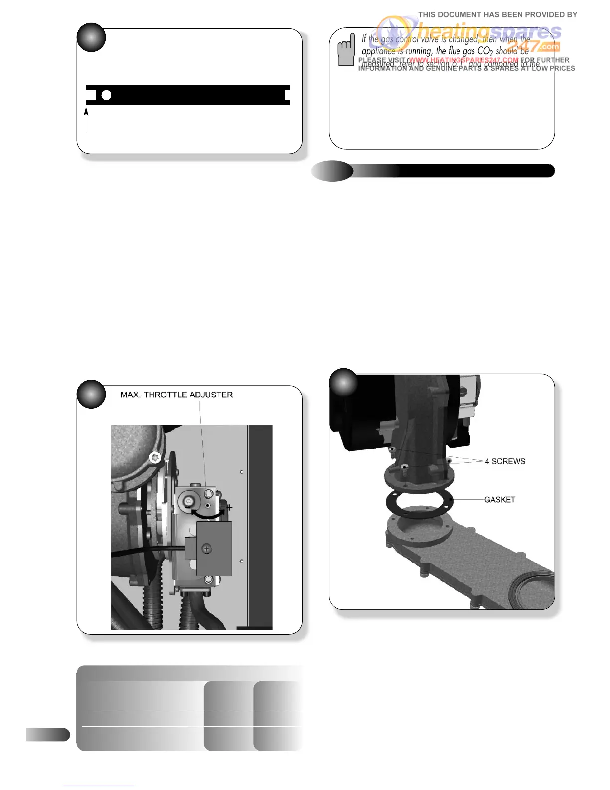
9.4
FAN
Refer to Figures 36 & 39
a)
Ensure supply voltage is isolated, and that the gas supply is
isolated.
b) Remove the gas control valve, fan & burner assembly; refer to
section 6.2.
c) Remove the gas control valve; refer to section 9.3.
d) Unscrew the three screws holding the gas valve mounting
plate, remove plate; refer to Figure 36.
e) Unscrew the four screws holding the fan to the burner
manifold, and remove fan; refer to Figure 39.
f) Attach and secure the replacement fan, replace the gasket.
g) Re-assemble in reverse order; ensure that all joints and seals
are correctly re-fitted.
39
THROTTLE ADJUSTMENT TOOL
Use this end for Nat Gas