45
35
Note: It is likely that there will still be some water
spillage when the head is removed.
Refer to Figure 46
a)
Ensure supply voltage is isolated.
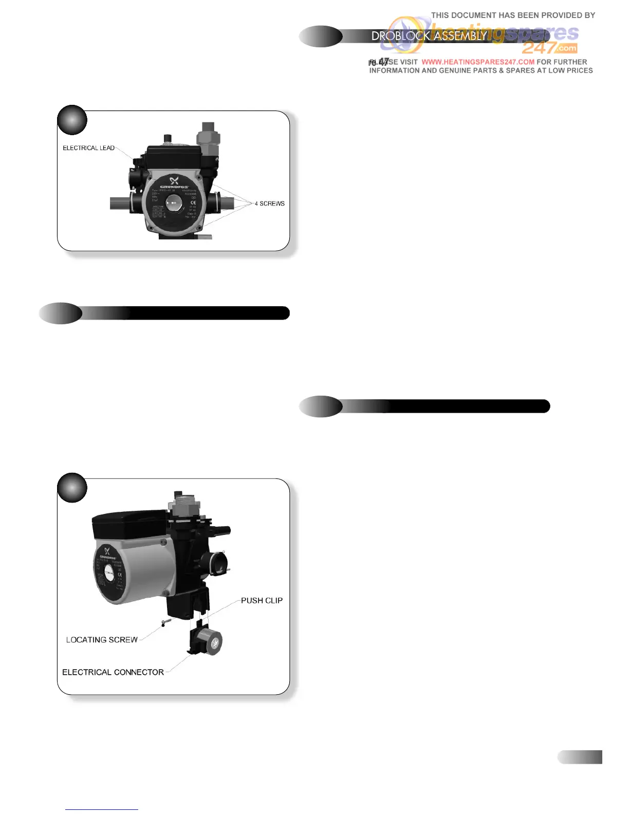
b) Disconnect the electrical lead to the diverter valve motorised head.
c) Unscrew the locating screw; refer to Figure 45.
d) Unclip the diverter valve motorised head and slide it down to
disengage it from the hydroblock body.
e) Fit the replacement diverter valve motorised head.
f) Re-assemble in reverse order; ensure that all joints and seals are
correctly re-fitted.
Refer to Figure 47
a)
a) Ensure supply voltage is isolated.
b) Disconnect the electrical leads to the pump head and diverter
valve motorised head.
c) Drain down the appliance; refer to section 9.24.
d) Remove the flow and return pipes from the heat exchanger; refer
to section 9.8.
e) Remove the clip holding the hydroblock adaptor fitting in place,
and remove fitting.
f) Remove the clip holding the return pipe in place.
g) Undo the nut connecting the CH return pipe to the CH return
isolating cock, and disengage the CH return pipe from the hydroblock.
h) Undo the nut connecting the DHW return pipe to the plate heat
exchanger and disengage the DHW return pipe from the hydroblock.
i) Unscrew the three screws holding the hydroblock onto the
mounting studs, and remove the hydroblock.
j) Align the replacement hydroblock against the mounting studs and
secure using the three screws.
k) Re-assemble in reverse order; ensure that all joints and seals are
correctly re-fitted.
l) Open the isolating cocks and vent air from the system using the
manual air vent. Re-pressurise the system as necessary and check for
water leaks.
9.10
DIVERTER VALVE MOTORISED HEAD
a) Ensure supply voltage is isolated.
b) Drain down the appliance; refer to section 9.24.
c) Undo the nut holding the manual air vent to the expansion vessel
and disengage the link pipe from the heat exchanger by removing the
clip and pulling upwards through the grommet at the top or by
rotating out of the way.
d) Remove the upper expansion vessel retaining bracket.
e) Slide the expansion vessel forward and remove.
f) Slide the replacement expansion vessel in place.
g) Re-assemble in reverse order; ensure that all joints and seals are
correctly re-fitted.
h) Open the isolating cocks and vent air from the system using the
manual air vent. Re-pressurise the system as necessary and check for
water leaks.
9.12
EXPANSION VESSEL
9.11
HYDROBLOCK ASSEMBLY
46
f) Re-assemble in reverse order; ensure that all joints and seals are
correctly re-fitted.
g) Open the isolating cocks and vent air from the system using the
manual air vent. Re-pressurise the system as necessary and check for
water leaks.