9.5
BURNER
Refer to Figures 34, 40 & 41
a)
Ensure supply voltage is isolated, and that the gas supply is
isolated.
b) Remove the gas control valve, fan & burner assembly; refer to
section 6.2.
c) Unscrew the three Torx screws, (T-25), holding the manifold to the
combustion chamber door, and remove the manifold; refer to Figure
34.
d) Remove the gasket, and withdraw the burner; refer to Figure 39.
e) Fit replacement burner, taking care not to damage the insulation,
and ensure burner is correctly located by lining up the locating tab.
f) Fit new gasket; refer to Figure 40.
g) Re-assemble in reverse order; ensure that all joints and seals are
correctly re-fitted.
40
41
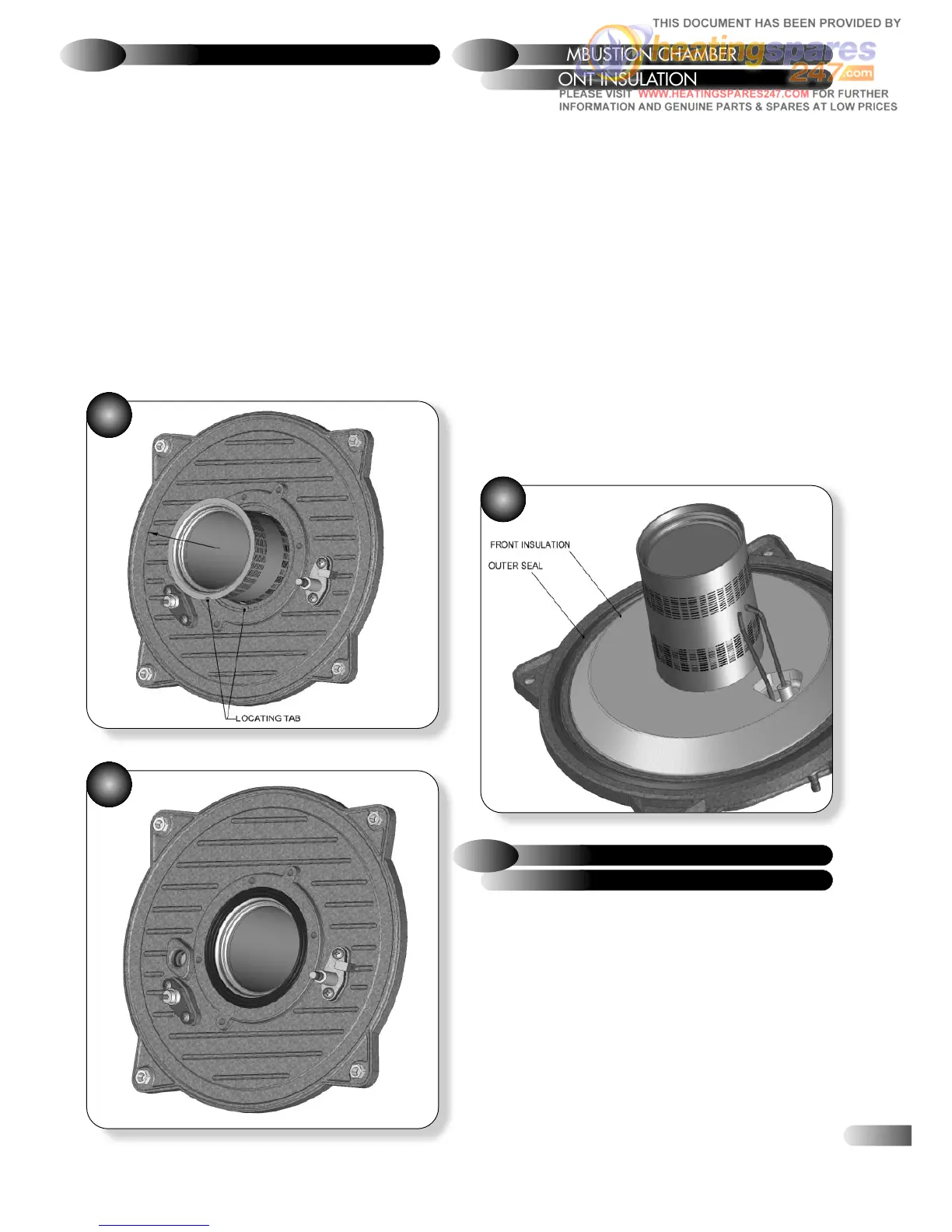
The design of the appliance is such that the combustion chamber
insulation should not require replacement unless mechanically
damaged. It is recommended that to prevent dust, the insulation is
dampened prior to removal, and that a protective mask is worn
when changing or handling the insulation material.
Refer to Figure 42
a)
Ensure supply voltage is isolated, and that the gas supply is
isolated.
b) Remove the gas control valve, fan & burner assembly; refer to
section 6.2.
c) Remove the electrodes; refer to section 9.1.
d) Remove the burner: refer to section 9.5.
e) Replace the combustion chamber front insulation.
f) Re-assemble the burner and electrodes, using new gaskets.
g) Check the position of the electrodes: refer to section 6.4.
h) Re-assemble in reverse order; ensure that all joints and seals are
correctly re-fitted.
FRONT INSULATION
9.6
COMBUSTION CHAMBER
42
Refer to Figure 43
a)
Ensure supply voltage is isolated, and that the gas supply is
isolated.
b) Remove the gas control valve, fan & burner assembly; refer to
section 6.2.
c) Use an Allen key to undo the central screw holding the rear
insulation in place.
d) Remove old insulation and fit replacement, ensuring locating
washer is in front.
e) Re-assemble in reverse order; ensure that all joints and seals are
correctly re-fitted.
REAR INSULATION
9.7
COMBUSTION CHAMBER
33