9.8
HEAT EXCHANGER
If thermal fuse has activated (open circuit and
error code ‘5’) the heat exchanger must be
replaced.
!
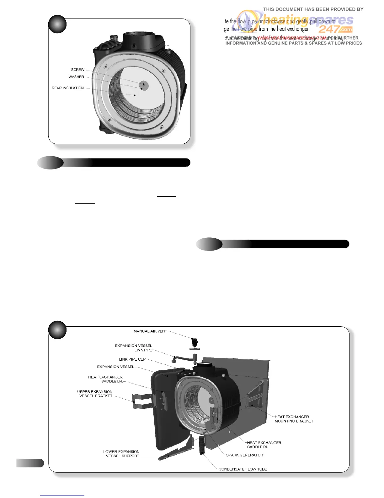
Refer to Figures 15, & 44
8
44
34
43
g) Rotate the flow pipe anticlockwise and gently pull down to
disengage the flow pipe from the heat exchanger.
h) Remove the retaining clip from the heat exchanger return inlet,
and undo the nut connecting the return pipe to the hydroblock
adaptor fitting.
i) Rotate the return pipe clockwise and gently pull down to
disengage the return pipe from the heat exchanger.
j) Disconnect the condensate drainpipe from the condensate drain
adaptor; refer to section 6.6.
k) Undo the nut holding the manual air vent to the expansion vessel
and disengage the vent from the heat exchanger by removing the
clip and pulling upwards through the grommet at the top.
l) Remove the 2 screws retaining the spark generator to the right
hand saddle bracket.
m) Remove the 2 screws retaining the expansion vessel upper
bracket to the left hand saddle bracket.
n) Remove the 4 screws that retain both the left and right saddle
brackets to the heat exchanger mounting brackets; refer to Figure 44.
o) Remove the saddle brackets and slide the heat exchanger
forwards and out.
p) Re-assemble in reverse order; check integrity of the flow and
return pipe ‘O’ rings and fibre washers and replace as necessary.
Ensure that all joints and seals are correctly re-fitted.
q) Open the isolating cocks and vent air from the system using the
manual air vent. Re-pressurise the system as necessary and check for
water leaks.
a) Ensure supply voltage is isolated, and that the gas supply is
isolated.
b) Remove the gas control valve, fan & burner assembly; refer to
section 6.2.
c) Disconnect the electrical leads to the flue sensor, flow sensor,
return sensor and thermal fuse.
d) Drain down the appliance; refer to section 9.24.
e) Disconnect the flue system from the appliance, 4 screws, and lift
up to disengage the flue from the flue adaptor; refer to Figure 16.
f) Remove the retaining clip from the heat exchanger flow outlet,
and undo the nut connecting the flow pipe to the plate-to-plate heat
exchanger.
9.9
PUMP (HEAD ONLY)
Refer to Figure 45
a)
Ensure supply voltage is isolated.
b) Disconnect the electrical lead to the pump head.
c) Drain down the appliance; refer to section 9.24.
d) Using a long Allen key unscrew the four screws holding the
pump head; refer to Figure 44.
e) Remove the pump head, and fit replacement pump head, using
a new ‘O’ ring seal.