37
49
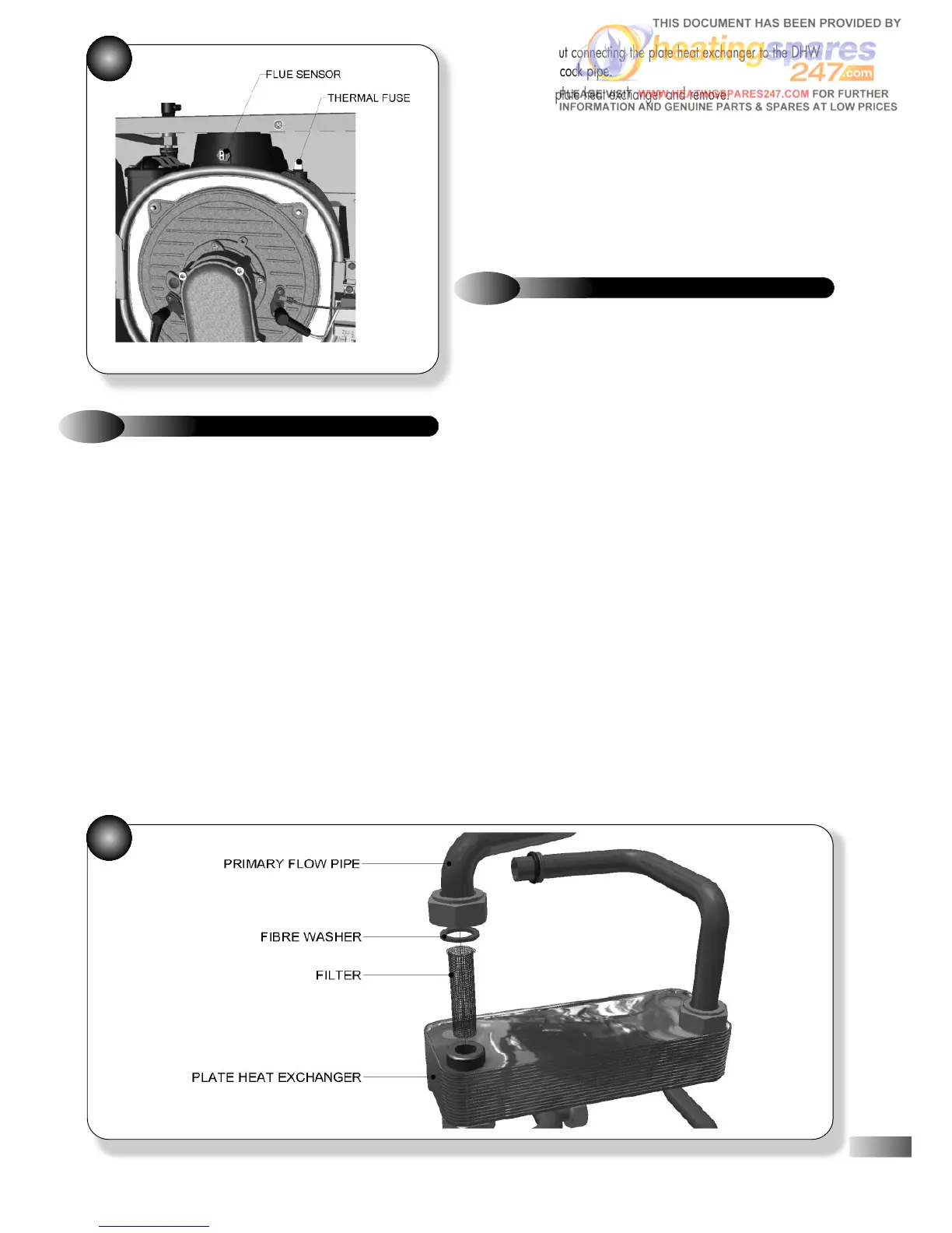
Refer to Figure 50
a)
Ensure supply voltage is isolated.
b) Drain down the appliance; refer to section 9.24.
c) Close the DHW inlet isolating cock, open a DHW tap at the
lowest point in the system and allow the pressure to dissipate. Close
this tap again.
d) If it is suspected that the plate heat exchanger is blocked or is
leaking then proceed as follows:
e) Undo the nut connecting the flow pipe from the main heat
exchanger to the plate heat exchanger.
f) Undo the nut connecting the pipe from the hydroblock to the
plate heat exchanger, and rotate out of the way.
g) Undo the nut connecting the plate heat exchanger to the CH
flow water isolating cock pipe.
h) Undo the nut connecting the plate heat exchanger to the DHW
outlet pipe.
9.16
PLATE HEAT EXCHANGER
i) Undo the nut connecting the plate heat exchanger to the DHW
water isolating cock pipe.
j) Lift up the plate heat exchanger and remove.
k) Fit the replacement plate heat exchanger, using new case seals
as necessary, ensuring the filter is fitted correctly.
l) Re-assemble in reverse order; ensure that all joints and seals are
correctly re-fitted.
m) Open the isolating cocks and vent air from the system using the
manual air vent. Re-pressurise the system as necessary and check for
water leaks.
8
50
9.17
CONDENSATE DRAIN SYSTEM
Refer to Figure 27
a)
Ensure supply voltage is isolated.
b) Open the drain sump cap, while holding a receptacle beneath
to capture any condensate.
c) Disconnect the condensate drainpipe from the appliance.
d) Detach the condensate drainpipe from the heat exchanger sump
adaptor, by gently pulling down.
e) Remove the condensate drain system, clean or replace as
necessary.
f) Re-assemble in reverse order; ensure that all joints and seals are
correctly re-fitted.