Technical Manual VERSION 2.0 -10-18-2018
48
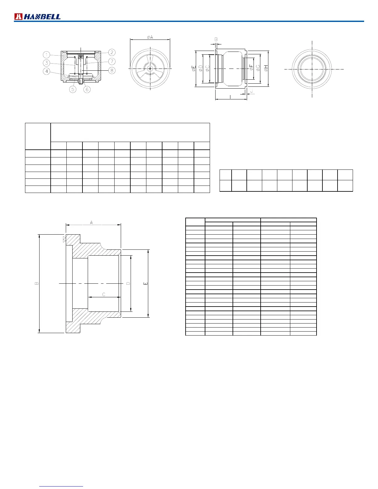
Figure 26 Discharge check valve outline drawing (Horizontal type)
Dia.
Dimension unit: mm
A B C D E F G H I J
1 1/2″
″″
″
86 4 55 59 76 42 60 75 80.5 6
2” 102 4 65 69 91 53 70 90 85 6
2 1/2″
″″
″
122 4 85 89 111 67 90 110 97 6
3″
″″
″
138 4 95 99 121 80 100 120 108 6
4″
″″
″
163 4 120 124 146 96 125 145 123 6
6” 238 5 190 195 216 146 190 215 160 6
d. Suction and discharge connection bushings
Figure 27 Flange bushing dimensions
Note: The above table lists specification of standard bushing for every model of Hanbell compressors. Their
dimensions correspond to flange bushing dimensions and the table below. If bushing dimensions are not
indicated in purchasing order, Hanbell will provide standard type. Suitable piping of customers’ choice is also
shown in the table below. If nonstandard bushing is needed, please doublecheck with Hanbell sales
representatives when placing order for compressors.
No.
1 2 3 4 5 6 7 8
Item
Body
C clipper
Spring
Valve
plate
Gasket
Nut
Guide
seat
Shaft
Standard Discharge Flange Bushing
Standard Suction Flange Bushing
Steel pipe Copper pipe Steel pipe Copper pipe
RC2100
1 1/2″
1 5/8”
2″
2 1/8”
RC2140
1 1/2″
1 5/8”
2″
2 1/8”
RC2180
1 1/2″
1 5/8”
2 1/2″
2 5/8”
RC2200
1 1/2″
1 5/8”
2 1/2″
2 5/8”
RC2230
2 ″
2 1/8”
3″
3 1/8”
RC2260
2 ″
2 1/8”
3″
3 1/8”
RC2300
2 ″
2 1/8”
3″
3 1/8”
RC2310
2 ″
2 1/8”
3″
3 1/8”
RC2320
2 ″
2 1/8”
3″
3 1/8”
RC2340
2 1/2″
2 5/8”
4″
4 1/8”
RC2370
2 1/2″
2 5/8”
4″
4 1/8”
RC2410
2 1/2″
2 5/8”
4″
4 1/8”
RC2430
2 1/2″
2 5/8”
4″
4 1/8”
RC2470
2 1/2″
2 5/8”
4″
4 1/8”
RC2510
3″
3 1/8”
4″
4 1/8”
RC2550
3″
3 1/8”
4″
4 1/8”
RC2580
3″
3 1/8”
4″
4 1/8”
RC2620
3″
3 1/8”
5″
5 1/8”
RC2710
4″
4 1/8”
5″
5 1/8”
RC2790
4″
4 1/8”
5″
5 1/8”
RC2830
4″
4 1/8”
5″
5 1/8”
RC2930
4″
4 1/8”
5″
5 1/8”
RC21020
4” 4 1/8” 6”
RC21130
4” 4 1/8” 6”
RC21270
5” 8”
RC21530
5” 8”