Technical Manual VERSION 2.0 -10-18-2018
65
B:Pt100 / Pt1000
(Option)
A:PTC
Earth Bolt
1/U
3/W
2/V
A
B
7/Z
9/Y
8/X
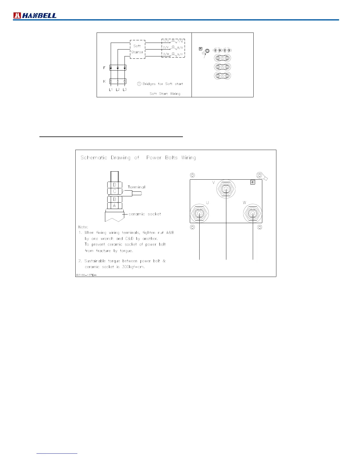
Figure 57 Soft starting diagram
Besides Y∆ and PWS start, if there were any inquiry of direct on line start、soft start、inverter start or series
reactance reduced voltage start, please contact Hanbell for further information.
Power supply wiring application (RC21270 and 1530 only)
To assure that power supply wiring to starter panel is properly installed and connected, please review and follow the
guidelines:
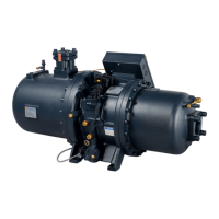
Figure 26: Power bolt connection
a. Power source application
(1) Verify that nameplate ratings are compatible with the power supply of the system.
(2) Use copper conductors to connect the power supply.
(3) Size the power supply wiring of the compressor: maximum current in required operating condition x 1.25
(25% safety factor).
(4) Make sure that incoming power wiring is properly phased; each power supply conduit connects to each
conductor in correct sequence to ensure equal phase representation as number 123 in order.
(5) Use flexible conduit to enhance serviceability and minimize transmission of vibration.
(6) Size the circuit breaker or fuse according to NEC or local guidelines.
(7) As install the power supply conduit, make sure that its position does not interfere with any compressor
components, or with other equipments.
b. Accessories for connection between the starter and the motor
(1) Grounding wire terminal lugs are provided inside the motor terminal box.
(2) Terminal clamps are supplied with motor terminals to accommodate standard motor wire terminal lugs.
c. Wire terminal lugs
(1) Use adequate size wire terminal lugs for the application.
(2) Carefully choose the size of wire lugs for compatibility with the conductor sizes specified by the electrical
engineer
(3) Use copper washers on power bolt connections.
(4) Tighten each bolt to 300kgfcm
(5) These connections should be completed under supervision of a qualified engineer in compliance with NEC
or local guidelines