43
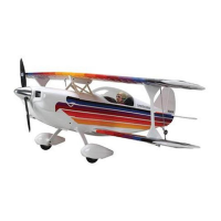
Step 17
Connect the pull-pull cable to the steering arm using
two crimps. Pass the cable through a crimp, through
the fasteners then back through the crimp. Use crimping
pliers to secure the crimps on the wire.
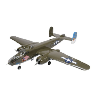
Step 18
Center the nose gear and steering servo. Thread a clevis
on the threaded rigging couplers and attach them to the
steering servo arm. Make sure to cut a 1/4-inch (4mm)
piece of heat shrink tubing for each of the clevises and
slide them into position. Mark where the cable crosses the
hole in the fastener.
Step 19
Repeat the crimping process, aligning the marks made
on the cable with the hole in the fastener. Cut any excess
cable using side cutters.
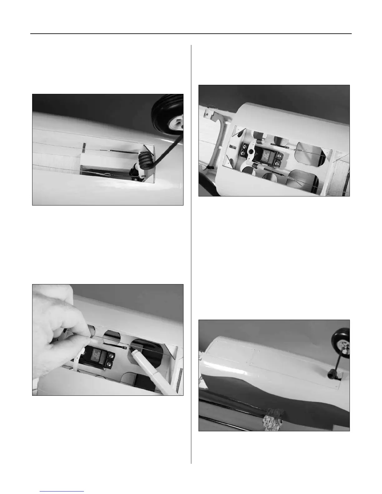
Step 20
Place the doors in position and drill a 1/16-inch
(1.5mm) hole 1/8-inch (3mm) from the corners of the
steering servo and nose gear doors. Remove doors and
apply a few drops of thin CA into each hole of the doors
and the mounting tabs in the fuselage to harden the
surrounding wood.
Step 21
Secure the doors over the steering servo and nose gear
with eight #2 x 3/8-inch sheet metal screws at each corner
of the doors.
Section 7: Fixed Landing Gear Installation