64
Required Parts
• Tail assembly • Pushrod connector
• Clevis1 • Y-harness
• Servo w/hardware • #8 washer
• 8-32 blind nut
• 8-32 x 1-inch socket head bolt
• 24-inch (610mm) servo extension
• 1
1
/
8
x 1/4-inch (28mm x 4mm) dowel
• Elevator pushrod wire, 36-inch (915mm)
Required Tools and Adhesives
• Drill • Thin CA
• 30-minute epoxy
• Hex driver: 9/64-inch
• Drill bit: 1/16-inch (1.5mm), 5/32-inch (2mm)
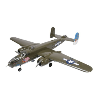
Step 1
Use 30-minute epoxy to glue the 1
1
/
8
x 1/4-inch
(28mm x 4mm) dowel into the hole in the leading
edge of the stabilizer.
Step 2
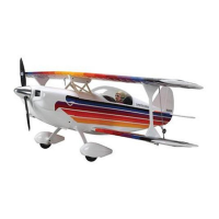
Use a short 8-32 socket head bolt, 9/64-inch hex
driver and washer to draw the blind nut into the
fuselage as shown.
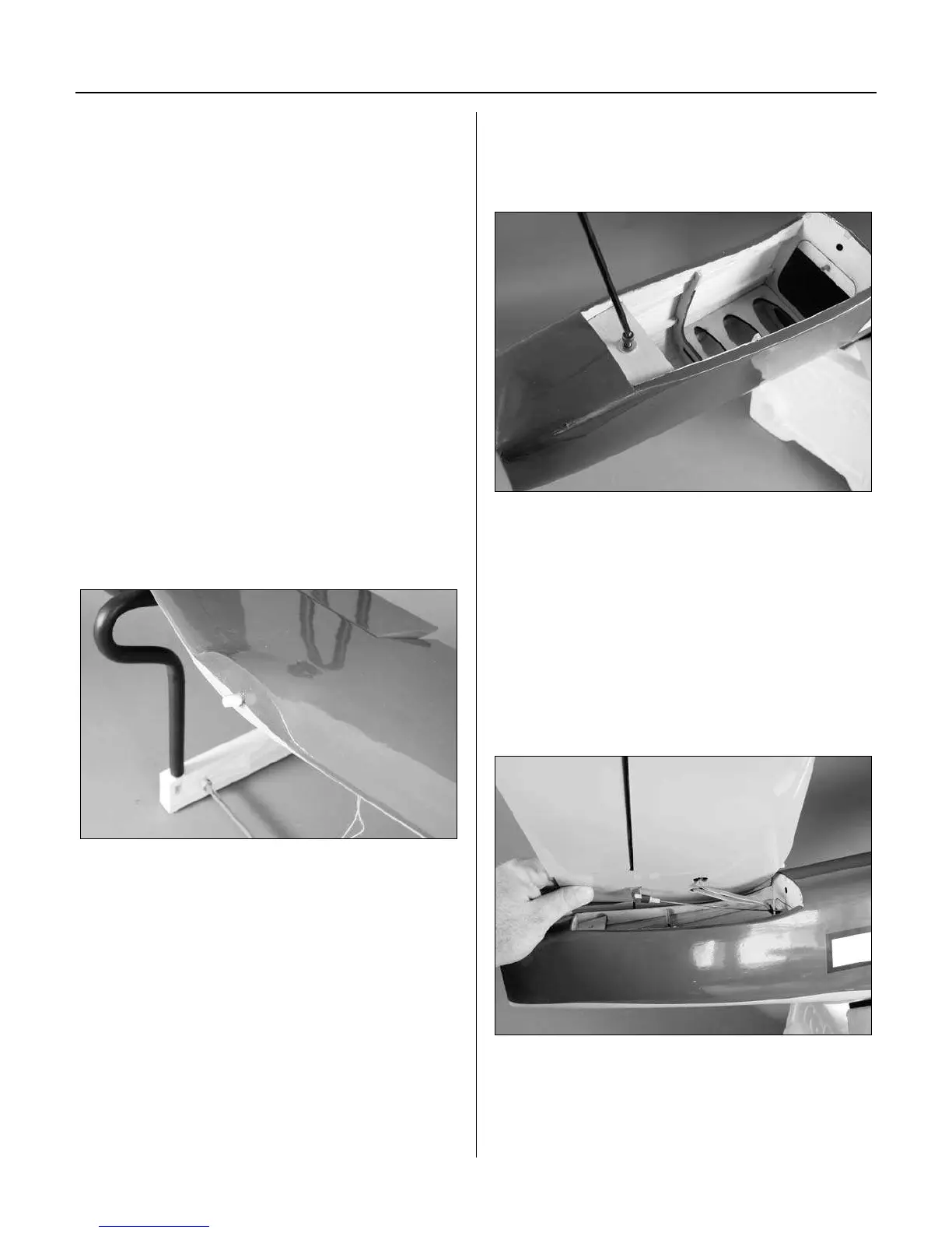
Step 3
Connect the Y-harness and 24-inch (610mm) servo
extension to the rudder servos and pass them into the
radio compartment. Make sure to secure all connections
so they will not become unplugged inside the fuselage.
Cut a 1/4-inch (4mm) piece of heat shrink tubing and
slide it onto a clevis. Thread the clevis onto the elevator
pushrod wire and attach the clevis to the elevator control
horn. The pushrod then goes into the pushrod tube pre-
installed in the fuselage.
Section 13: Tail Section Installation