74
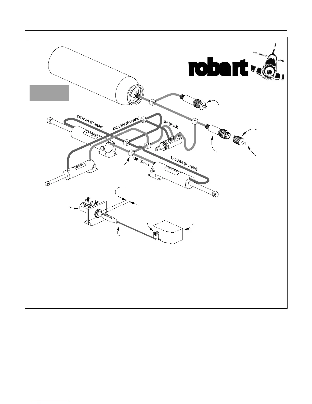
3 GEAR
INSTALLATION
Retaining nuts
are
optional
Right Landing
Gear Cylinder
Nose
Gear
Cylinder
Tee
Fittings
Left Landing
Gear Cylinder
Optional On-board
Pressure Gauge #173
Servo
Arm
Link Rod
Assembly
Control
Valve
1/4" Travel
Maximum
Servo
Fill Valve
(AIR SUPPLY IN)
Fill Chuck
ss
(NOT INCLUDED)
Included in the
VRX Kits
Retract Air line Routing Diagram
Note: The link rod between
the servo arm and the control
valve spool is very important.
Use a nylon clevis at the valve
spool and a simple Z-bend at
the servo arm as shown. The
throw on the servo arm should
allow for approximately 1/4-inch
(4mm) of travel. This will keep
any excessive side loads on the
valve spool minimal and, in turn,
prevent any leakage around the
valve spool seals.
** USE THE PROPER LINK ROD ASSEMBLY
FOR THE CONTROL VALVE
(servo, servo arm, and link rod assembly are NOT
included in kit)