21
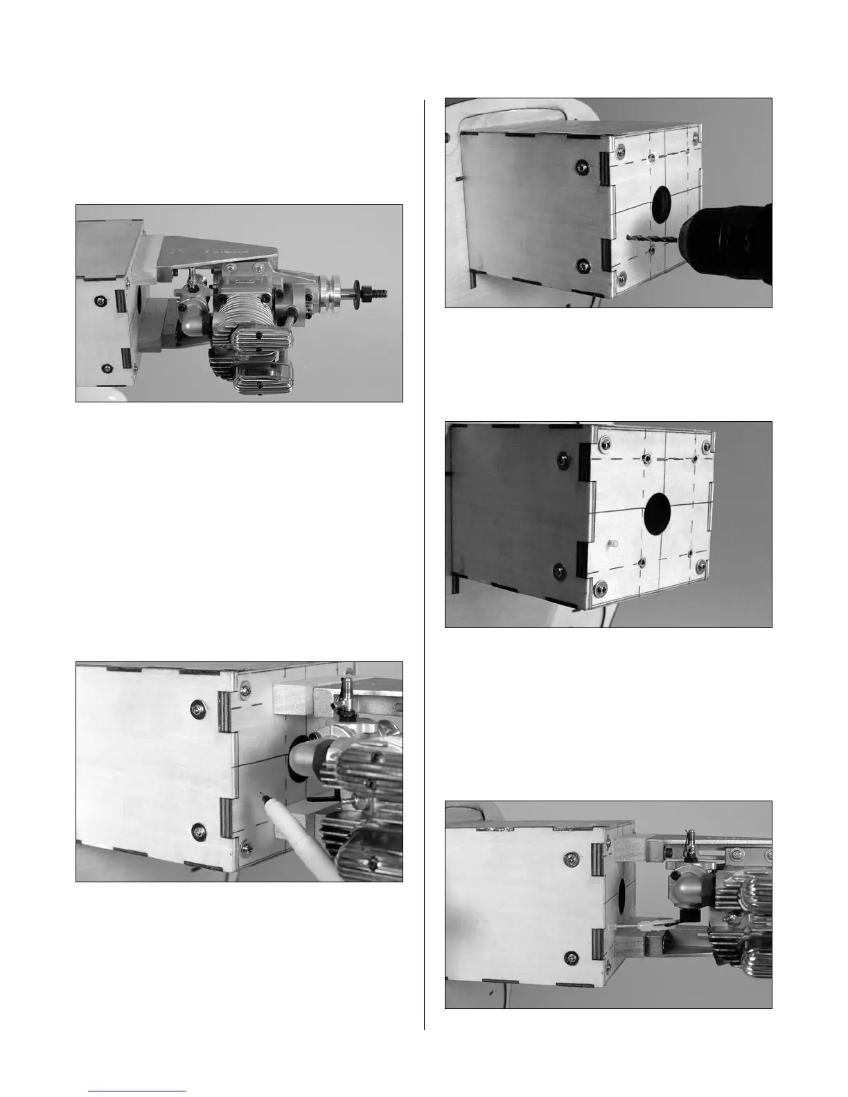
Step 9
Attach the engine to the firewall using four
8-32 x 1
1
/
2
" socket head bolts, four #8 washers and
four 8-32 blind nuts. Remember to use the mounting
blocks that were prepared in Steps 1 and 2.
Step 10
Check the distance from the firewall to the drive
washer and adjust as necessary to the distance of
6
7
/
8
". Also double-check that the engine is square
to the firewall.
Step 11
Determine the proper location for the throttle pushrod.
Mark the location with a felt-tipped pen. Remove
the engine and drill the firewall for the pushrod tube
using a drill and 5/32" drill bit.
Step 12
Roughen the tube using medium sandpaper. Slide
the tube into position and use medium CA to glue it
to the firewall.
Step 13
Trim the tube 1/2" in front of the throttle servo tray.
Place a 1/4" piece of fuel tubing onto a clevis, then
thread the clevis onto the 13
3
/
4
" throttle pushrod.
Attach the clevis to the carburetor arm. Slide the
pushrod wire into the tube and secure the engine to
the firewall.
Section 7A – Engine Installation: Saito