35HARDI
®
New NAVIGATOR OPERATOR’S MANUAL
Maintenance
Hoses and tubes
Check all hoses and tubes for possible damage and
proper attachment. Replace damaged hoses or tubes.
1000 Hours / Yearly Service
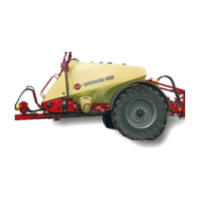
Wheel bearings
Check the condition of the bearings the following way:
1 Place stop wedges in front of and behind the left
hand wheel and jack up the right hand wheel.
2 Support the trailer with axle stands.
3 Remove the wheel.
4 Remove the hub cap (A
Fig 36
), cotter pin
(B
Fig 36
) and castle nut (C
Fig 36
).
5 Pull off wheel hub. Use a wheel puller if necessary.
6 Check roller bearings for discoloration and wear
- replace if worn or damaged.
7 Assemble the hub and bearings using a new sealing
ring (D
Fig 36
).
8 Fill the hub and bearings with fresh grease before
fi tting to the shaft.
9 Fit castle nut. Rotate hub and tighten the castle nut
until a slight rotation resistance is felt.
10 Loosen the castle nut again until the fi rst notch is
aligned with the cotter pin hole in the shaft.
NOTE! The shaft has a vertical and a horizontal
cotter pin hole. Use the one fi rst aligned with the
notch when loosening the castle nut.
11 Fit a new cotter pin and bend it.
12 Fill the hub cap with fresh grease and carefully
press it onto the hub.
13 Fit the wheel again and tighten the wheel nuts.
(Refer
50 Hours / Weekly Service
(Page 34) for
torque wrench setting. Tighten all bolts to half
the specifi ed torque fi rst, then to the full specifi ed
torque.
14 Tighten again after 10 hours of work. Check the
torque every day until it is stabilized.
15 If you do not feel totally confi dent changing wheel
bearings, contact your HARDI
®
dealer’s workshop.
Occasional maintenance
Maintenance and replacement intervals for the next
points depend very much on conditions under which
sprayer operates, and are therefore impossible to
specify.
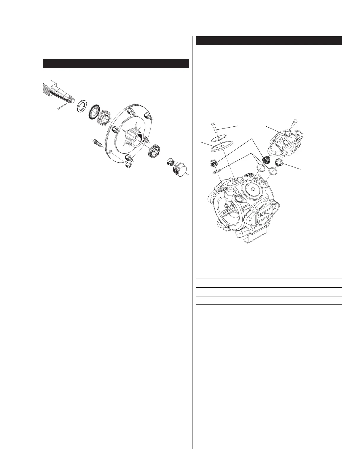
Pump valves and diaphragms replacement
(363/463 pumps)
NOTE! It is recommended that if one or more
diaphragms and/or valves need replacing they all
should be replaced
Diaphragm pump overhaul kit (valves, seals,
di a phragms, etc.)
Pump model HARDI
®
part No.
363 750342
463 750343
Changing valves
1 Remove the valve covers (A
Fig 37
). Before
chang ing the valves (B & B1
Fig 37
) note their
orientation so they are replaced correctly.
2 The two white fl ap valves (B1
Fig 37
) must be
placed in the valve openings as shown. It is
rec om mend ed to use new O-rings (C
Fig 37
) when
chang ing or checking the valves.
Changing diaphragms
1 With the valve covers removed as explained above,
remove the diaphragm bolts (D
Fig 37
).
2 The diaphragms (E
Fig 37
) may now be changed.
3 If fl uids have reached the crankcase, re-grease the
pump thoroughly. Also check the drain hole at the
bottom of the pump is not blocked.
E
A
B
B1
C
D
A = Valve Cover
B = Valves
B1 = White Flap Valves
C = O-rings
D = Di a phragm Bolt
E = Diaphragm
A
B
C
D
Fig 36
Fig 37
 Loading...