ACS-160 Series & STL-160 Series T1 Multiplexer Installation & Operation 1 – Introduction
Version 2.11, August 2011
1-2 Harris Corporation
Intraplex Products
1.2 Manual Use
Keep in mind that all references in this manual to the 3RU ACS-160 Series multiplexers are equally
applicable to the STL-160 Series multiplexers. For general information, use these guidelines:
Readers Unfamiliar with the ACS-160 Series Multiplexers: You can use this manual as a tutorial
by reading or skimming all sections in order.
Installers: If you are already familiar with the ACS-160 Series multiplexers, go directly to Section 3 –
“Installation and Wiring” for step-by-step installation instructions. Otherwise, you should read at least
the rest of this introductory section before beginning.
Transmission and Planning Engineers: Section 4 – “Setup & Configuration” gives ACS-160 Series
configuration guidelines. Section 5 – “Remote Control Operation” gives information and procedures for
using interfaces to remotely configure and operate an ACS-160 Series or STL-160 Series multiplexer.
T1 input/output, power, and other specifications appear in Section 7 – “Specifications.”
Maintenance Technicians: If you are already familiar with the ACS-160 Series multiplexers, go
directly to Section 6 – “Testing and Troubleshooting” for test procedures and troubleshooting
guidelines. Otherwise, you should review Sections 1 through 5 before proceeding to Section 6.
Individual channel module manuals give test procedures for the specific channel modules shipped with
this system. Diagnostic and control access is also available remotely from a PC or dumb terminal.
1.3 Multiplexer Configurations
The ACS-160 Series and STL-160 Series multiplexers consist of these models:
● ACS-163 (or STL-163) 3RU T1 terminal multiplexer
● ACS-165 (or STL-165) 3RU T1 drop and insert multiplexer
● ACS-166 (or STL-166) 3RU T1 dual terminal multiplexer
● ACS-167 1RU T1 terminal multiplexer
● ACS-168 1RU T1 drop and insert multiplexer
● ACS-169 1RU T1 dual multiplexer
All ACS-160 Series and STL-160 Series multiplexers are rack-mountable in EIA standard 19" racks.
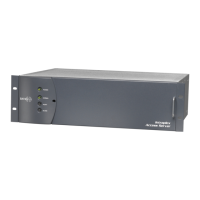
Full size, “3RU” shelves (ACS-163, ACS-165, ACS-166, STL-163, STL-165, and STL-166) are 5¼" high
(Figures 1-1 and 1-2). Compact, “1RU” shelves (ACS-167, ACS-168, and ACS-169) are 1¾" high
(Figure 1-3).
The 1RU versions perform the same functions as their 3RU counterparts but differ in the
● Number of channel modules they can accommodate
● Type of power supply used
● Physical orientation of the modules in the shelf
● Connection points for alarm relays and a ring generator
These differences are pointed out in the appropriate sections throughout this manual.
Note: The ACS-166 and ACS-169 Dual Terminal Access Servers use different midplanes from those
used in the ACS-163 Terminal Access Server, ACS-165 Drop and Insert Access Server, ACS-
168 Drop and Insert Access Server, STL-163 Studio-to-Transmitter Link, and STL-165 Studio-
to-Transmitter Link multiplexers. It is not possible to use these five multiplexers as dual
terminal access servers.
The ACS-163 and ACS-167 terminal multiplexers each terminate one T1 circuit. The ACS-165 and
ACS-168 multiplexers each terminate two T1 circuits and allow channels to pass between the two
circuits as well as to terminate at the multiplexer.

 Loading...