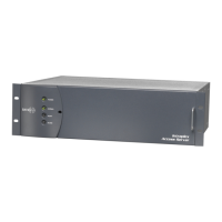
A-ISiCL CM-5RTD Delay Configuration ACS-160 Series & STL-160 Series T1 Multiplexer
Version 2.1, April 2011
Harris Corporation A-3
Intraplex Products
Table A-2. Delay Feature S Codes
S
Code
Binary Digits
Valu
e Description 1 2 3 4 5 6 7 8
S01 B 0 0 0 0 0 0 0 0
Phase-locked loop (PLL) status.
0 PLL is locked (LOCK indicator light is on).
1 PLL is not locked (LOCK indicator light is off).
B 0 0 0 0 0 0 0
0 Buffer status
0 Normal (BUFFER indicator light is off).
1 Overflow/underflow in previous second (BUFFER
indicator is on). Note: the BUFFER indicator light
reacts instantly, while the buffer status bit remains
“1” for about a second after the event.
B 0
0
0
0
0
0
0 0 Not
Used
S02 B 0 0 0 0 0 0 0 0
0 or 1 The most significant bit of the programmed delay
setting.
B 0
0
0
0
0
0
0
0 Not
Used
S03 B 0
0
0
0
0
0
0
0
0 or 1 The second through ninth most significant bits of the
programmed delay setting.
S04 B 0
0
0
0
0
0
0
0
0 or 1 The eight least significant bits of the programmed
delay setting.
A.3 CM-5RTD Operation
The CM-5RTD module has a set of indicator lights located behind the TIMING indicator lights (Table A-
3).
Table A-3. CM-5RTD Indicator Lights
Indicator Description
BUF Buffer. This yellow light turns on when the delay buffer overflows or underflows, indicating the
input clock frequency is going outside the PLL lock range.
LOCK This green light turns on when the actual delay is identical to the configured delay.
SRVC This green light turns on when the delay functionality is activated.
The number of bits used in the buffer determines the delay setting. The buffer depth can range from 6
bits to 131,076 bits. Each T1 (1.544 Mbps) bit has a duration of 647.67 nanoseconds, allowing you to
set a delay time ranging from 3.89 microseconds to 84.00 milliseconds. The delay is set by sending a
17-bit binary number to the CM-5RTD module; the module takes this number, adds five to it, and uses
the result to set the buffer depth in bits.
The 17-bit number can be sent to the CM-5RTD module in two ways — through the RS-232 serial
remote port using ISiCL P codes (Section A.4 – Delay Setting with RS-232 Remote Port), or using the
RS-422 control “port” (Section A.5 – Delay Setting with RS-422 Control Port).
Warning! Valid numbers are binary 00000000000000001 through 11111111111111111 (1 through
131,071 decimal). Do not send all zeroes.

 Loading...