MM-015371-001, Rev. C
40
8 CONTROL HEAD MECHANICAL INSTALLATION
8.1 GENERAL INFORMATION
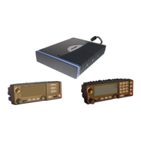
The radio must be connected to a control head to provide the operator-to-radio interface. Two different
control heads are available — the CH-721 Scan model and the CH-721 System model. See Figure 8-1 and
Figure 8-2 respectively. The CH-721 Scan model control
head features three (3) large menu selection
buttons. The System model control head has a 12-button keypad to allow advanced operations without the
need of a DTMF-capable microphone.
Figure 8-3 on page 41 illustrates the rear panel of the two control head models. Both models have
identical rear panels and rear panel connectors.
Figure 8-1: CH-721 Scan Model Control Head Front Panel
(Other controls are same as shown for Scan model.)
Figure 8-2: CH-721 System Model Control Head Front Panel
The CH-721 control heads feature a large easy-to-read 3-line graphical vacuum fluorescent display, an
on/off/volume control knob, menu controls and buttons, trunking mode buttons, an emergency/home
button, a scan on/off/volume control, and three (3) preset buttons. Other front panel components include a
microphone connector and LED-type indictors. One LED indicator is the busy indicator that lights when
3-Line Graphical Vacuum
Fluorescent Display
Microphone Connecto
On/Off/
Volume
Control
System/
Group/
Channel
Selection
Control
/ Ramp Control
Preset/
Softkey
Buttons
Emergency/
Home Button
+/- Ramp Control
Ambient Light-Level Sensor
Transmit
and Busy
Indicators
Scan On/Off Button
Clear Button
Menu Button
Option Button
12-Button Keypad
Clear Button
Menu Button
Option Button

 Loading...