2900 Selma Highway, Montgomery AL 36108 USA
PH: +1.334.386.5400 (option 2) FAX: +1.334.386.5450 WEB: www.hartzell.aero
Page | 13
MM10001
Dated 1/1/08
Rev L dated 5/21/15
A
B
C
D
D
CONVEX
END DOME
EXHAUST
COMBUSTION
CHAMBER/FLAME TUBE
BAFFLES
HEAT
EXCHANGER
CROSSOVER
MIXER ASSEMBLY
HEAD
ASSEMBLY
FUEL
INJECTOR
REVOLVING
SPARK
FUEL SUPPLY
INCOMING
COMBUSTION
AIR
IGNITOR
JACKET
E
E
HEATED AIR
VENT/FRESH AIR
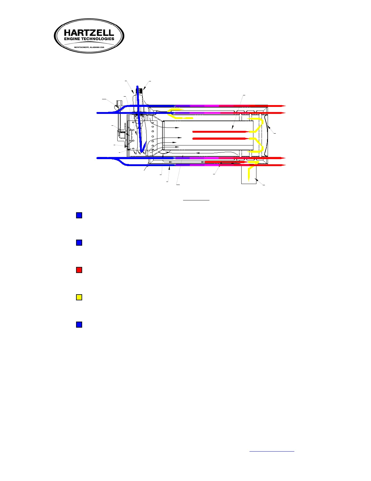
FIGURE 2
A. Combustion Air Supply. This is provided by way of an external ram air scoop and or a blower
assembly independent of the vent/fresh air supply. Combustion air enters the head assembly, and
then is metered into the mixer chamber.
B. Ignition is supplied via high-voltage oscillating current, this coupled with the igniter design, create
a revolving continuous spark located in the head assembly. This igniter is positioned in the path of
an internal fuel injector designed to atomize the fuel at a pre-determined pressure.
C. This ignited fuel/air mix is then dragged from mixer assembly as additional combustion air
channels through the head assembly into the combustion chamber portion of the liner. The
majority of combustion is created at this point in the combustion chamber or flame tube area.
D. The flame travels full length of the flame tube hitting the end dome, it then doubles back along the
inside wall and on into the outer layer of the heat exchanger. The spent gasses again travel the
length of the tube around a series of baffles then exiting out the exhaust.
E. Air for the ventilation system is picked up via an external ram air scoop and/or a blower assembly
typically mounted on the inlet end of the jacket. Air is forced through the heated external passages
of the combustion chamber. Ventilating air thus comes in contact with the heated cylindrical
surfaces subsequently pushing heated air into the cabin.