2900 Selma Highway, Montgomery AL 36108 USA
PH: +1.334.386.5400 (option 2) FAX: +1.334.386.5450 WEB: www.hartzell.aero
Page | 32
MM10001
Dated 1/1/08
Rev L dated 5/21/15
9.4 REASSEMBLY
Except for parts that have already been reassembled and tested as subassemblies, generally follow
the reverse order of the index number in the ‘illustrated parts breakdown’ when reassembling the
heater. Use all new gaskets, filters, seals and O-rings.
CAUTION: Fasteners securing components to heater must be as specified in the illustrated parts
breakdown.
NOTE: Use caution in protecting nozzle face. Any deviation of the original contour will alter the
spray pattern. The nozzle must be replaced if this occurs.
NOTE: Do not use Teflon products as a fitting sealer anywhere in the fuel system.
9.4.1 Mixer
Before installing combustion head mixer assembly in combustion tube, coat gasket
with Permatex
1372W High Temperature Form-A-Gasket or equivalent. Also
apply a small amount to the threads of the mounting screws.
9.4.2 Assemble jacket to combustion tube.
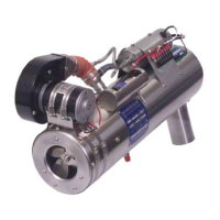
9.4.3 Nozzle Holder
Insert O-ring 20692 into groove on nozzle side of holder.
FIGURE 17
distort or be damaged
in any way.
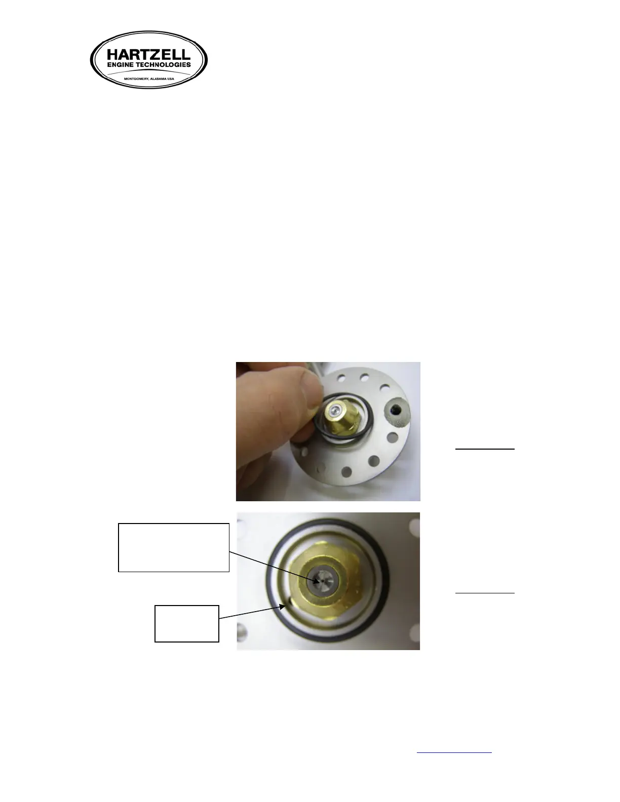
FIGURE 18
drain port