2900 Selma Highway, Montgomery AL 36108 USA
PH: +1.334.386.5400 (option 2) FAX: +1.334.386.5450 WEB: www.hartzell.aero
Page | 42
MM10001
Dated 1/1/08
Rev L dated 5/21/15
11.4.5.2 Description of operation
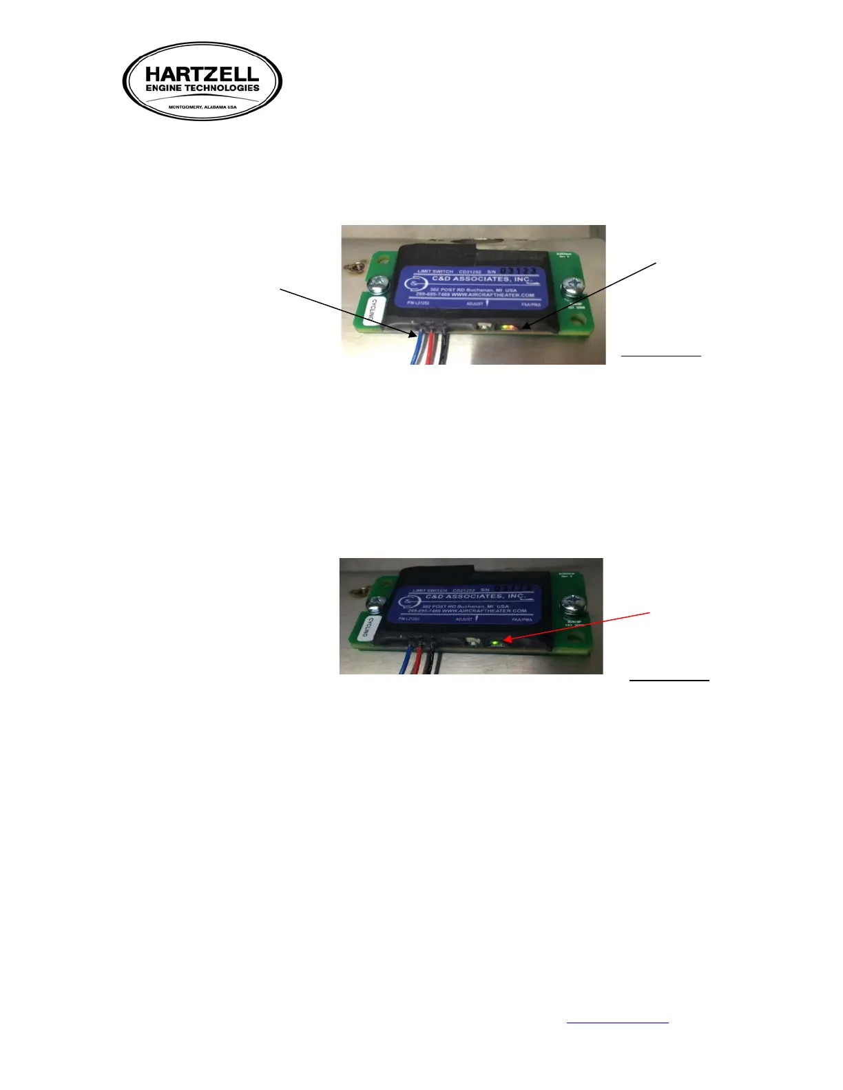
11.4.5.2.1 The switch is equipped with three wires, a red power supply wire, a
black ground wire and a blue power out wire to activate the fuel
solenoid.
11.4.5.2.2 The switch is also equipped with two LED lights located next to the
adjustment screw, one red and one green.
• The green lamp indicates the CD21252 has power being
supplied on the red wire. This can be a 12 VDC or 24VDC.
NOTE: Make certain a good ground is obtained.
• The red lamp indicates the switch is calling for heat and thus
supplying line voltage to the blue wire of the switch, which is
attached to the fuel solenoid of the heater.
11.4.5.2.3 The red light also helps to diagnose a system fault. If the blue wire
has shorted internally the red light will blink repeatedly. Once a
ground fault has been recognized by the switch, its internal circuitry
shuts off power to the blue wire until the ground fault is repaired.
Red power supply wire
Black ground wire
LED Lights
Red light off
Indicates “heat
off”