2900 Selma Highway, Montgomery AL 36108 USA
PH: +1.334.386.5400 (option 2) FAX: +1.334.386.5450 WEB: www.hartzell.aero
Page | 35
MM10001
Dated 1/1/08
Rev L dated 5/21/15
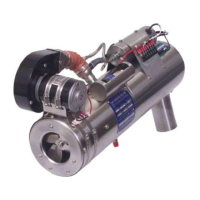
Adjust fuel pump pressure to 8psi. (6.5psi min, 10psi max) (100 psig +5 for jet fuel).
Close heater switch. The heater should ignite within five seconds.
The duct switch or thermostat should control the outlet temperature from around 50° to
225
°F.
NOTE: This is dependent on air flow and ambient temperature.
10.4 DETERMINING AND SETTING HEAT OUTPUT
10.4.1 Install a temperature probe (min 0-500˚ F) in the outlet plenum 6-8” aft of the heater. A
good location would be approx. 6” aft of the heater or near the thermostat sensor.
Usually you can find a small access point somewhere in the ducting aft of the heater
CAUTION: Verify thermal couple is not touching plenum internal wall.
10.4.2 Setting upper limit temperature upper limit switch
10.4.2.1 If your heater is equipped with a CD21252…..
Place a 6” 20G jumper wire with 2 small alligator clips (or the like) across the heater
terminal strip numbers 2 and 3 for terminal strips numbered 1-6 or 7 and 8 for
terminal strips numbered 4-10, which will bypass the aircraft thermostat.
NOTE: Be sure not to short any other terminals.
With the heater running, verify that the outlet plenum temp. is set properly. Adjust
the temperature of the heat duct outlet distribution plenum as follows:
• For non-pressurized aircraft set switch to a low of 215º and a high of 255º.
• For pressurized aircraft set switch to a low of 190˚ and a high of 225˚.
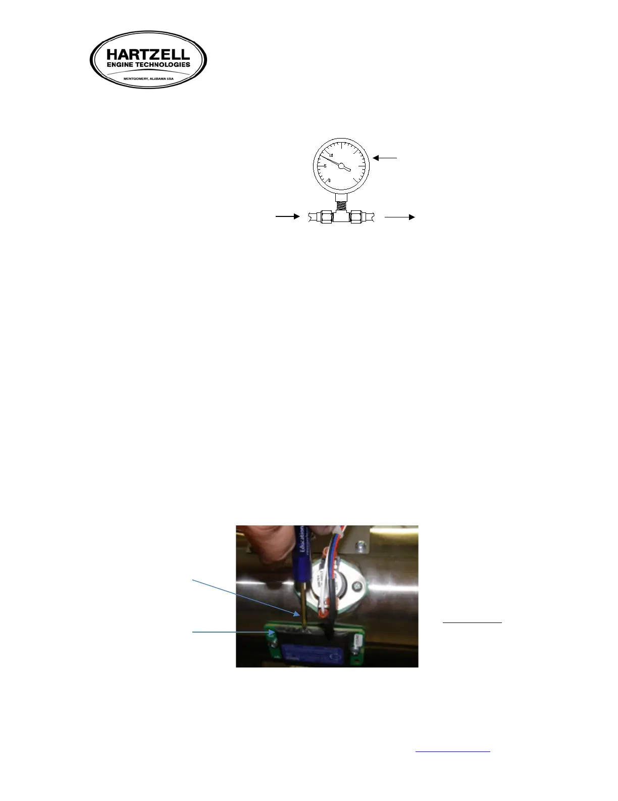
NOTE: Adjustment is made by rotating a small 1/16” screw located next to the wires on the side
of the switch. It may have a dab of inspectors lacquer over the screw. Rotation
clockwise one turn will increase temperature approx. 20° F. Decrease temperature by
turning counterclockwise.
SUPPLY
PRESSURE
SWITCH P/N
CD21252
adjustment
FIGURE 21