2900 Selma Highway, Montgomery AL 36108 USA
PH: +1.334.386.5400 (option 2) FAX: +1.334.386.5450 WEB: www.hartzell.aero
Page | 39
MM10001
Dated 1/1/08
Rev L dated 5/21/15
11.2 TROUBLESHOOTING - COMBUSTION HEATER SYSTEM
NOTE: Full system voltage (12 and/or 24-volt DC) must be present at the heater for trouble-shooting
sequence. CAUTION – Low Voltage will cause premature failure of ignition unit, electronic
switches, etc., or may cause low or no fuel pressure. Verify voltage at heater with voltmeter
prior to going any further in the outlined trouble shooting sequence.
Tools needed - Volt/OHM meter, 0-500° temperature monitor, #2 Phillips & 3/32 square tip screw
driver, 3/ 4” open-end wrench, a 7/8” deep well spark plug socket with ratchet (0-15 PSI f or AV
Gas, 0-200 PSI for Jet fuel), fuel pressure gauge with jumper wire (min 3”) and auxiliary power to
aircraft to supply rated system voltage.
Basic information - Three basic factors are needed for proper heater operation: Combustion air,
fuel and ignition. When one or more of these are missing, the heater will not function. Follow
missing item to its malfunction and correct it.
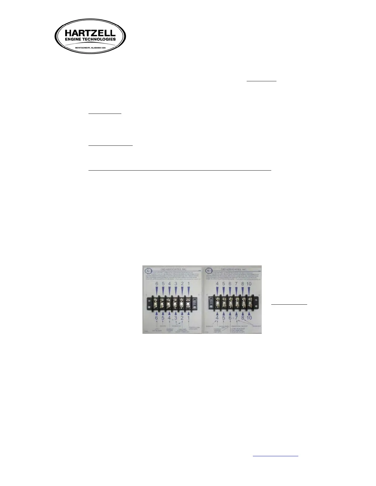
Terminal strips on heaters are numbered with four different configurations.
• Terminal strips numbered 1, 2, 3, 4, 5, 6 or 6, 5, 4, 3, 2, 1 have power present on terminals
numbered 1, 2, 3 and 6 when heat is called for. Terminal number 4 is generally for an
overheat light connection and terminal number 5 is always ground. In a very few heaters, a
ventilation blower is not incorporated in the heater and terminal number 6 has no wires. In
some installations the ventilation blower may receive power from terminal 6 through a
landing gear squat switch. Heat control is maintained by interrupting power to terminal
number 3 generally by a thermostat wired between terminals 2 and 3.
• Terminal strips numbered 4, 5, 6, 7, 8, 10 or 10, 8, 7, 6, 5, 4 have power present at 4, 6, 7, 8
and 10 when heat is called for. Heat control is maintained by interrupting power to terminal
number 8 and 10. Heat control is generally controlled by a thermostat wired from terminal 7
to 8.